Mask design method, program, and mask design system

Inactive Publication Date: 2013-10-03
GLOBALFOUNDRIES INC
View PDF3 Cites 2 Cited by
  • Summary
  • Abstract
  • Description
  • Claims
  • Application Information

AI Technical Summary

Problems solved by technology

Since OPC uses polygon domain and counter-biases the mask iteratively, it does not allow the modification of topology during optimization.
The fixed topology limits optimization performance.
The rule-based topology modification technology becomes less effective in the fabrication of state of the art semiconductor devices and human intuition may not provide an acceptable solution for the mask pattern.
The ILT technologies can contribute design manufacturability of the optical mask in the state of the art implementations; however, the ILT has some defects in the optimization of mask topology. FIG. 10 shows a plot of computation time and objective values of ruling (both in arbitrary units) and mask sampling rates (in arbitrary unit); the left hand ordinate represents the objective value; the right hand ordinate represents the computation time; the abscissa represents the sampling rate of the mask pixels.
Referring to FIG. 10, the ILT improves the objective value as the sampling rates of the pixels increase; however, the computation time for obtaining the corresponding objective values increases in a worse than linear relation with respect to the sampling rate, while the improvement in the objective value slows down in a likewise worse than linear relation to that of the computation time as well as to total runtime.
When object domain sampling is made at points on a coarse grid, corresponding to a low sampling ra

Method used


Image

  • Mask design method, program, and mask design system
  • Mask design method, program, and mask design system
  • Mask design method, program, and mask design system

Examples


Embodiment Construction

[0039]The present invention will be described based on preferred embodiments using drawings; however, the preferred embodiments are described for the purpose of description of the invention and the present invention should not be limited to the described embodiments.

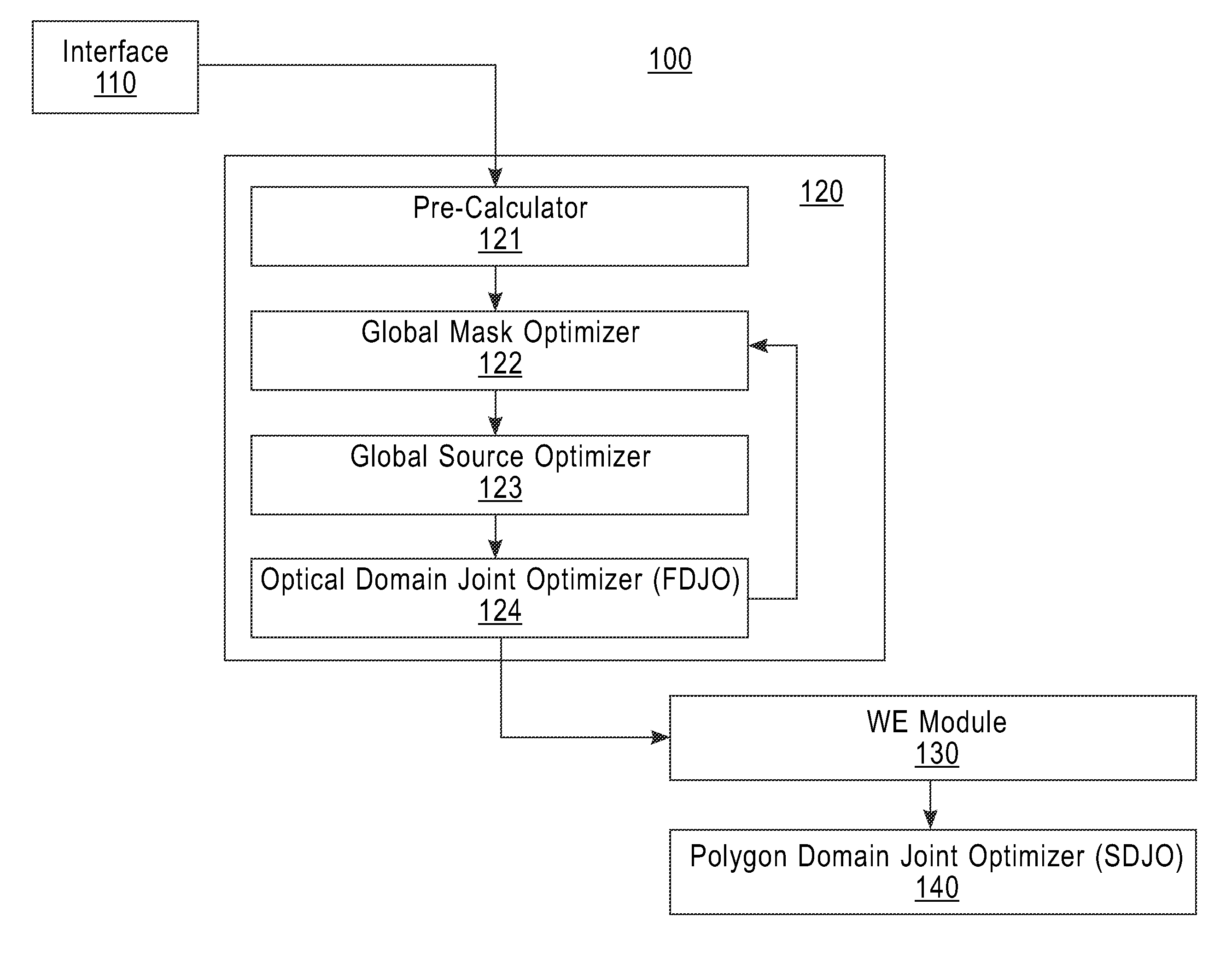
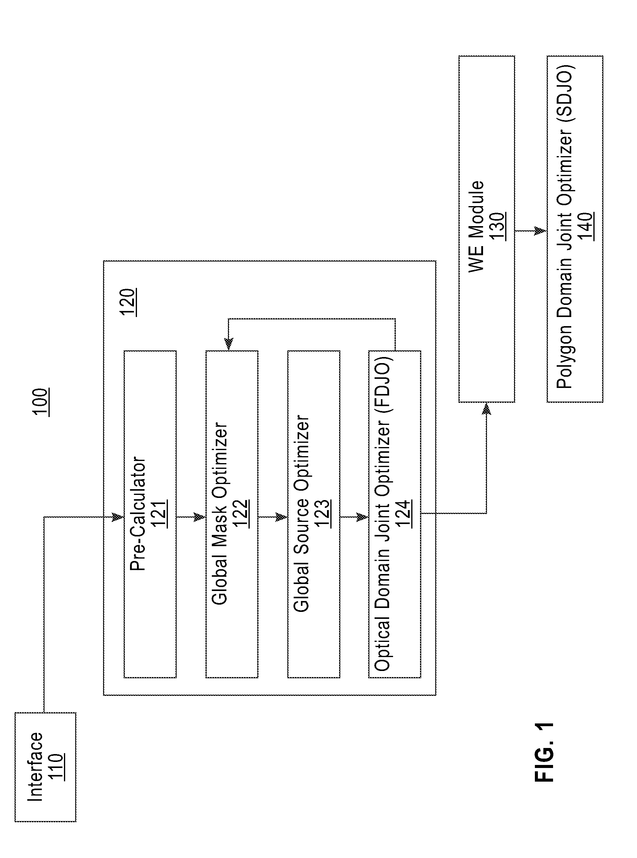
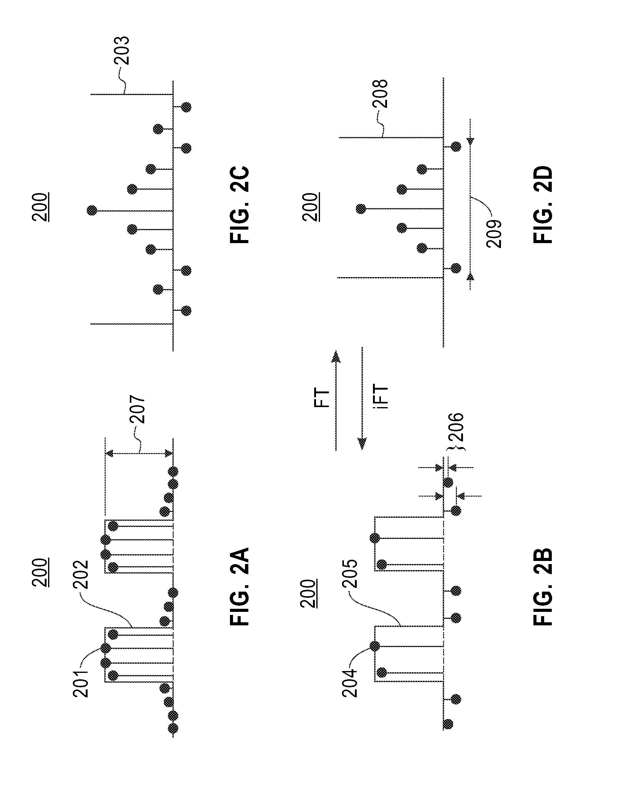
[0040]The present invention uses optical domain masks as variables during the SMO process optimization; however, the mask topology in the pupil domain is converted to the polygon domain expression at the later wavefront engineering step eventually in order to apply further improved mask optimization. In the optical domain, wavefronts are optimized according to SMO (Source Mask Optimization) technique, in a preferred embodiment.

[0041]In general, the invention includes a step in which a set of optical domain variables is generated to represent the mask wavefront during optimization, and these variables can be located in the object domain or in the pupil domain. In some embodiments, the present invention uses object domain ...


PUM


Abstract

A method, an article of manufacture, and a system for designing a mask. The method for designing a mask is implemented by a computer device having a memory, a processor device communicatively coupled to the memory, and a module configured to carry out the method including the steps of: generating an optical domain representation from a design pattern and an imaging light; and optimizing the optical domain representation under a constraint that values of negative excursions at predetermined evaluation points must be greater than or equal to predetermined negative threshold values assigned to the predetermined evaluation points; where: the optical domain representation is a variable representation of a wavefront; the imaging light is light that is transmitted through the mask; the negative excursions are in an object domain representation of the optical domain representation; and the predetermined evaluation points are in the object domain representation.

Description

CROSS-REFERENCE TO RELATED APPLICATION [0001]This application claims priority under 35 U.S.C. §119 from Japan Patent Application No. 2012-084657 filed Apr. 3, 2012, the entire contents of which are incorporated herein by reference.BACKGROUND OF THE INVENTION[0002]1. Field of the Invention[0003]The present invention relates to a mask design technology and more particularly relates to a mask design method, a program therefore, and a mask design system.[0004]2. Description of Related Art[0005]The entire contents of US Patent applications identified by Ser. Nos. 12 / 334,482, 12 / 334,488 each filed on Dec. 14, 2008; Ser. No. 12 / 334,485 filed on Dec. 14, 2008; and the entire contents of U.S. Pat. No. 8,108,802 issued on Jan. 31, 2012; and of U.S. Pat. No. 7,057,709 issued on Jun. 6, 2006; may be incorporated herein as references.[0006]Minimum printed feature sizes in semiconductor devices become finer due to continuous requirements for ever higher performance and faster operation of the dev...

Claims


Application Information

Patent Timeline
IPC IPC(8): G03F1/70
CPCG03F1/70
Inventor INOUE, TADANOBUMELVILLE, DAVID O.ROSENBLUTH, ALAN E.SAKAMOTO, MASAHARUTIAN, KEHAN
Owner GLOBALFOUNDRIES INC
Why Eureka
Try Eureka