Fiber machining device and assembling method for optical fiber connector

a technology of fiber machining and optical fiber connector, which is applied in the direction of optical elements, manufacturing tools, instruments, etc., can solve the problems of affecting the efficiency of data transmission of optical connectors and increasing light loss

Inactive Publication Date: 2013-10-10
HONG FU JIN PRECISION IND (SHENZHEN) CO LTD +1
View PDF7 Cites 2 Cited by
  • Summary
  • Abstract
  • Description
  • Claims
  • Application Information

AI Technical Summary

Problems solved by technology

However, the end surface of the field optical fiber may be scraped during the assembling process of the optical fiber and generate a plurality of depressions, crac

Method used


Image

  • Fiber machining device and assembling method for optical fiber connector
  • Fiber machining device and assembling method for optical fiber connector
  • Fiber machining device and assembling method for optical fiber connector

Examples


Embodiment Construction

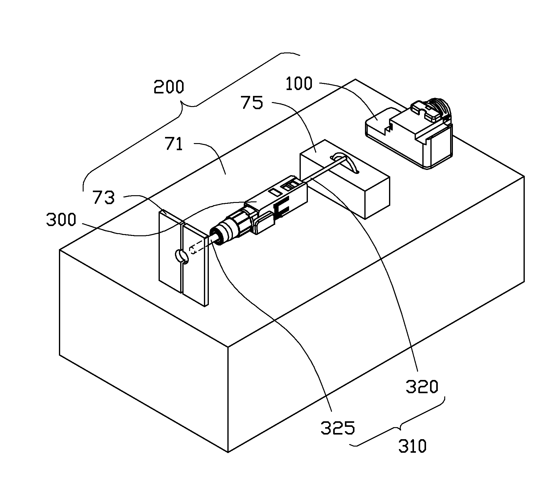
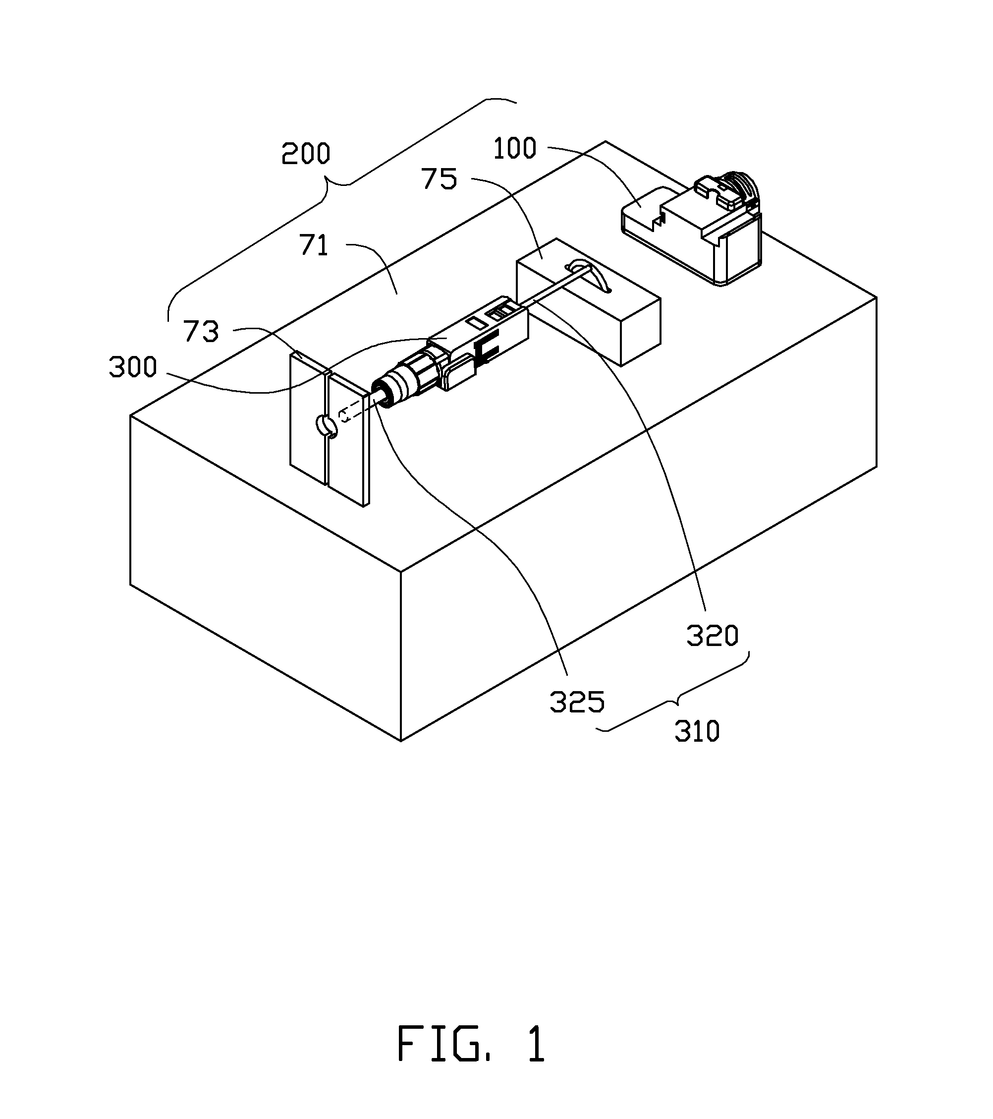
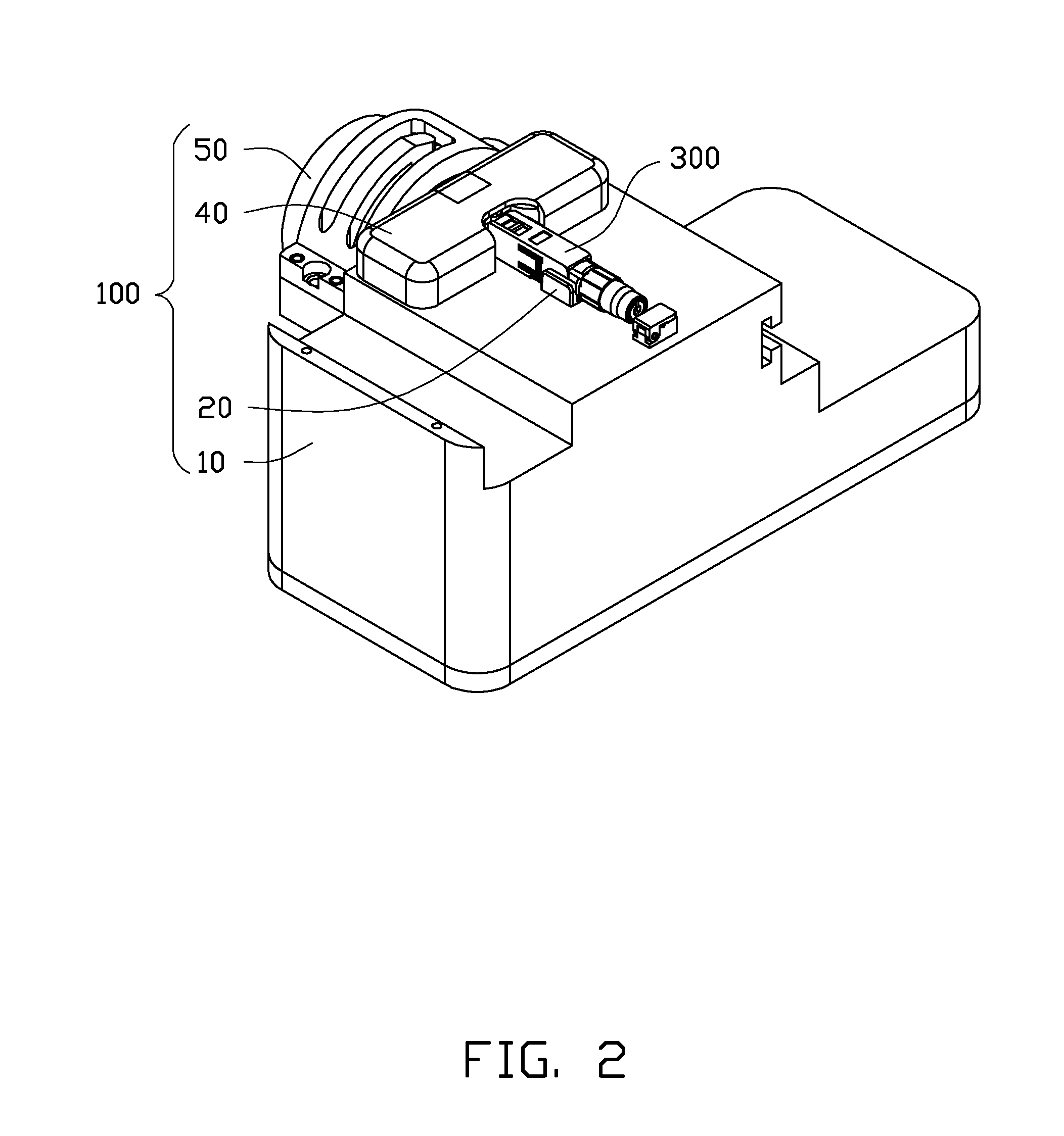
[0017]FIG. 1 shows an embodiment of a fiber machining device 200. The fiber machining device 200 is used for treating and assembling an optical fiber connector 300. The optical fiber connector 300 includes a cable 310 fixed in the optical fiber connector 300 and an optical fiber ferrule 330 (seen in FIG. 7) fixed in an end of the optical fiber connector 300. The cable 310 includes an optical fiber 320 and an outer coating 325 formed on the optical fiber 320. The optical fiber ferrule 330 axially defines a through hole 335 (seen in FIG. 7) for receiving the optical fiber 320.

[0018]The fiber machining device 200 includes a position table 71, a stripping tool 73, a cutting tool 75, and a fiber end surface machining mechanism 100. The stripping tool 73 is loaded at an end of the position table 71 for removing the outer coating 325 formed on the optical fiber 320 to expose the optical fiber 320. The cutting tool 75 is applied to the fiber machining device 200 for cutting the optical fibe...


PUM

PropertyMeasurementUnit
Lengthaaaaaaaaaa
Depthaaaaaaaaaa

Abstract

A fiber end surface machining mechanism includes a base seat, a pair of electrodes, and a fiber position structure. The fiber position structure includes a resisting unit and a driving member. The resisting unit is movably assembled on the base seat and is located between the pair of electrodes. The driving member is rotatably assembled on the base seat adjacent to the resisting unit. The driving member includes a cam portion resisting the resisting unit. When the cam portion rotates to drive the resisting unit to move towards an optical fiber connector, the resisting unit drives an optical fiber of the optical fiber connector to move relative to an optical fiber ferrule of the optical fiber connector, and a length of the optical fiber protruding out of the optical fiber ferrule is adjusted.

Description

CROSS-REFERENCE TO RELATED APPLICATIONS[0001]This application claims all benefits accruing under 35 U.S.C. §119 from China Patent Application No. 201210100975.2, filed on Apr. 9, 2012, in the China Intellectual Property Office, the disclosure of which is incorporated herein by reference. The application is also related to co-pending applications entitled, “OPTICAL FIBER CONNECTOR AND ASSEMBLING DEVICE FOR THE SAME” (Atty. Docket No. US45521); “FIBER END SURFACE MACHINING DEVICE AND FIBER POSITION STRUCTURE THEREOF” (Atty. Docket No. US45523); “OPTICAL FIBER CONNECTOR” (Atty. Docket No. US45525); “OPTICAL FIBER CONNECTOR” (Atty. Docket No. US45526); “OPTICAL FIBER CONNECTOR” (Atty. Docket No. US45528); “OPTICAL FIBER CLAMPING MECHANISM AND OPTICAL FIBER CONNECTOR USING THE SAME” (Atty. Docket No. US45529).BACKGROUND[0002]1. Technical Field[0003]The present disclosure relates to fiber machining devices, particularly to a fiber machining device and an assembling method for an optical f...

Claims


Application Information

Patent Timeline
IPC IPC(8): G02B6/25
CPCG02B6/25G02B6/3833Y10T29/52G02B6/2552Y10T29/49826G02B6/3898
Inventor LI, ZHI-MINGWEI, LE-PENGSUN, TAO
Owner HONG FU JIN PRECISION IND (SHENZHEN) CO LTD
Why Eureka
Try Eureka