System and method for controlling an exhaust system having a selective catalyst reduction component

a technology of catalyst reduction and exhaust system, which is applied in the direction of exhaust treatment electric control, machines/engines, mechanical equipment, etc., can solve the problems of difficult to determine with suitable accuracy, expensive and unreliable aging determination methods based on correlations with engine parameters that can be sensed, and inability to meet the requirements of vehicle aging

Inactive Publication Date: 2013-10-10
GM GLOBAL TECH OPERATIONS LLC
View PDF11 Cites 33 Cited by
  • Summary
  • Abstract
  • Description
  • Claims
  • Application Information

AI Technical Summary

Benefits of technology

[0009]In another exemplary embodiment of the invention, a system for controlling operation of an SCR component comprises a selective catalyst reduction (SCR) component diagnostic module that is configured for receiving a signal reflecting a sensed condition of an exhaust stream associated with the SCR component and for estimating an apparent aging time of the SCR component based on the sensed condition of the exhaust stream. A system for controlling operation of an SCR component also comprises an SCR component management module that is configured for selectively adjusting an operating condition of the SCR component based on the apparent aging time of the SCR component.

Problems solved by technology

Unfortunately, determining aging of an SCR component onboard a vehicle can be costly and unreliable.
Yet, SCR aging may actually be more closely related to substrate temperatures in the SCR component and to other conditions internal to the SCR component, conditions that can be difficult to determine with suitable accuracy.
Therefore, aging methods that are based on correlations with engine parameters that can be sensed can be costly, can require significant time to develop correlation data to fully characterize aging as a function of the numerous parameters affecting aging, and can be inaccurate if all significant variables are not considered.

Method used


Image

  • System and method for controlling an exhaust system having a selective catalyst reduction component
  • System and method for controlling an exhaust system having a selective catalyst reduction component
  • System and method for controlling an exhaust system having a selective catalyst reduction component

Examples


Embodiment Construction

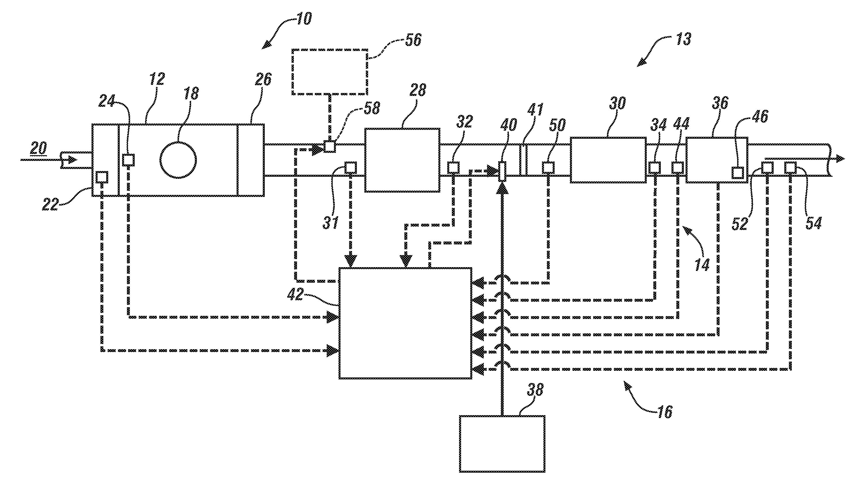
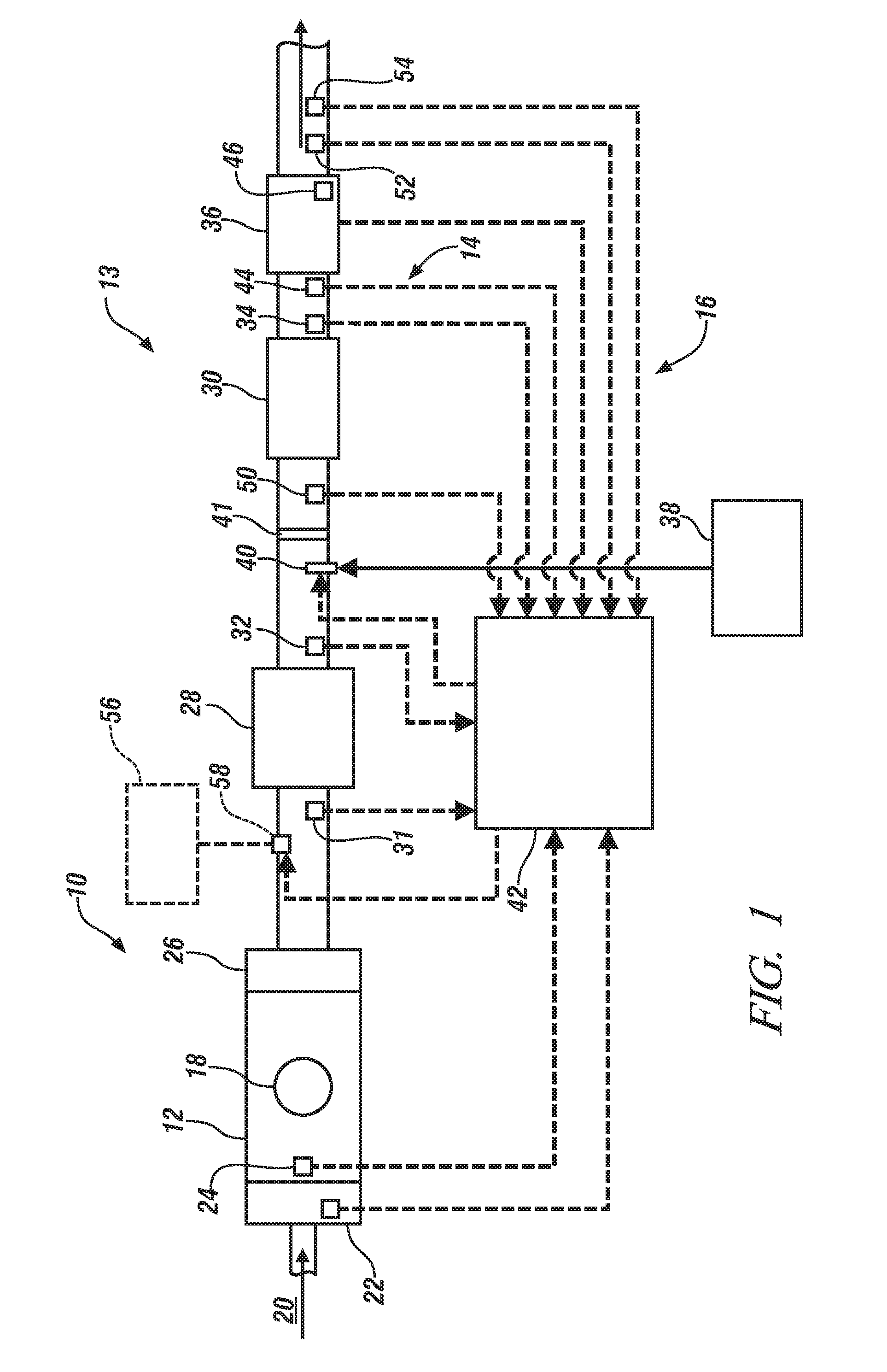
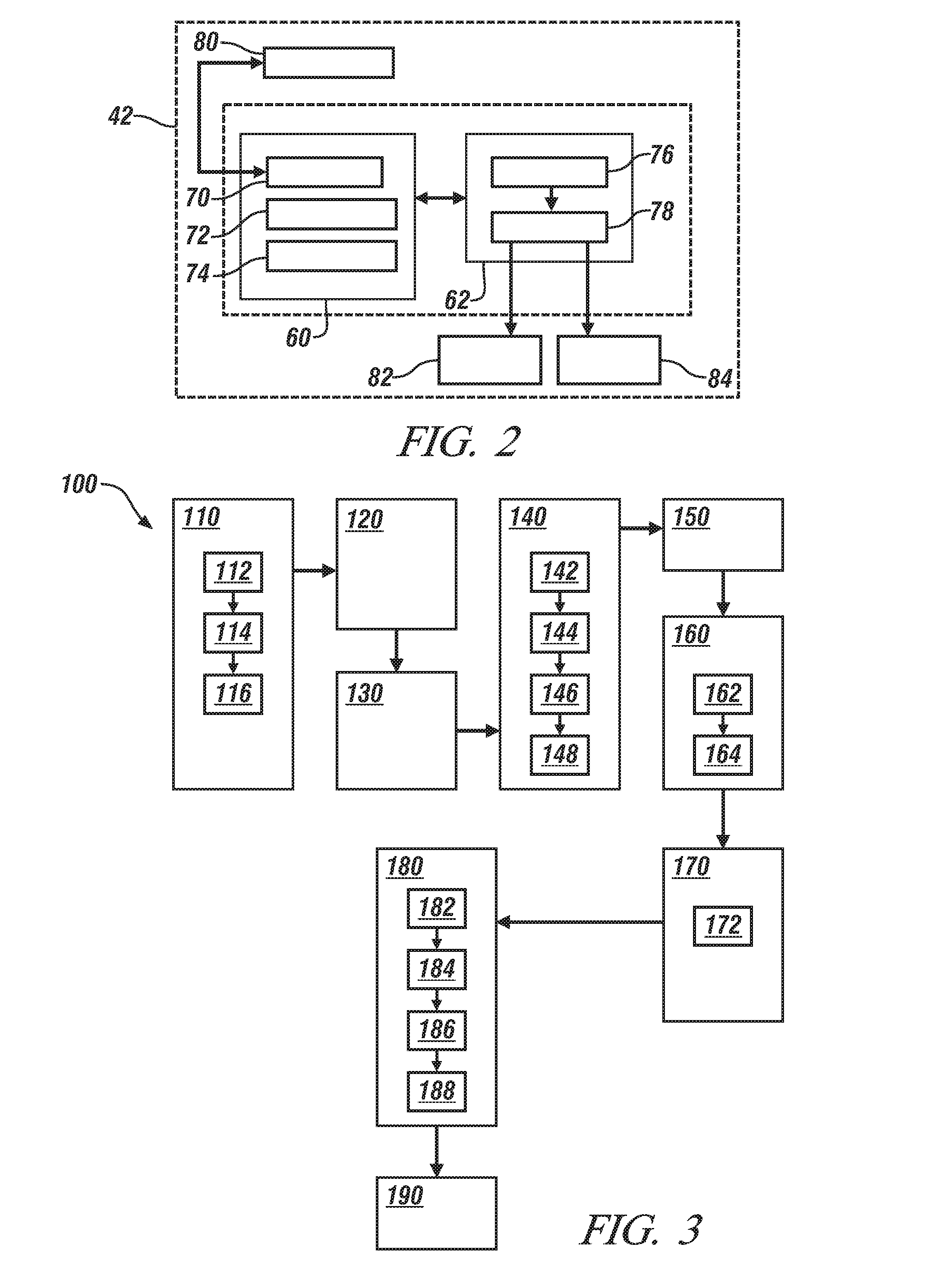
[0015]The following description is merely exemplary in nature and is in no way intended to limit the disclosure, its application, or uses. For purposes of clarity, the same reference numbers will be used in the drawings to identify similar elements. As used herein, the phrase at least one of A, B, and C should be construed to mean a logical (A or B or C), using a non-exclusive logical or. It should be understood that steps within a method may be executed in different order without altering the principles of the present disclosure.

[0016]As used herein, the term “module” refers to an Application Specific Integrated Circuit (ASIC), an electronic circuit, a processor (shared, dedicated, or group) and memory that execute one or more software or firmware programs, a combinational logic circuit, and / or other suitable components that provide the described functionality.

[0017]While the following disclosure involves diesel engines, other types of engines such as gasoline engines, including di...


PUM


Abstract

A method for controlling operation of an SCR component includes receiving a signal reflecting a sensed condition of an exhaust stream associated with the SCR component, estimating an apparent aging time of the SCR component based on the sensed condition of the exhaust stream, and setting an operating condition of the SCR component based on the apparent aging time of the SCR component.

Description

FIELD OF THE INVENTION[0001]The subject invention relates to vehicle exhaust systems, and more particularly to systems and methods for controlling exhaust systems that include a selective catalyst reduction (SCR) components.BACKGROUND[0002]The background description provided herein is for the purpose of generally presenting the context of the disclosure. Work of the presently named inventors, to the extent it is described in this background section, as well as aspects of the description that may not otherwise qualify as prior art at the time of filing, are neither expressly nor impliedly admitted as prior art against the present disclosure.[0003]During combustion in a diesel engine, an air / fuel mixture is delivered through an intake valve to cylinders and is compressed and combusted therein. After combustion, the piston forces the exhaust gas in the cylinders into an exhaust system. The exhaust gas may contain oxides of nitrogen (NOx) and carbon monoxide (CO).[0004]Exhaust gas treat...

Claims


Application Information

Patent Timeline
Patent Type & Authority Applications(United States)
IPC IPC(8): F01N11/00F01N3/20
CPCF01N11/00Y02T10/47Y02T10/24F01N3/106F01N3/2066F01N9/005F01N13/009F01N2550/02F01N2560/021F01N2560/026F01N2900/0412F01N2900/1402F01N3/035Y02T10/12Y02T10/40
Inventor SUN, MIN
Owner GM GLOBAL TECH OPERATIONS LLC
Why Eureka
Try Eureka