

cutter
- Summary
- Abstract
- Description
- Claims
- Application Information
AI Technical Summary
Benefits of technology
Problems solved by technology
Method used
Image

Examples
first embodiment
of the Invention
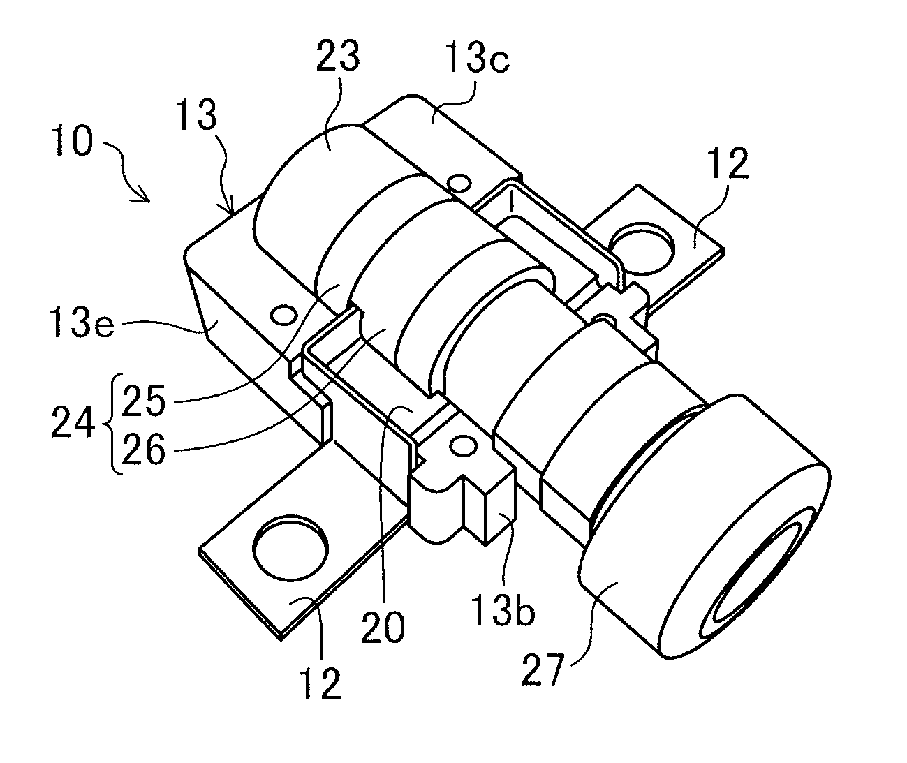
[0061]As shown in FIG. 1 to FIG. 5, a cutter (10) according to the first embodiment is configured to cut a harness (12), which comprises a current-carrying member of the present invention, by moving a blade (30) forward using high-pressure gas generated by a reaction of a gas-generating agent. The cutter (10) uses an explosive as the gas-generating agent for generating high-pressure gas.
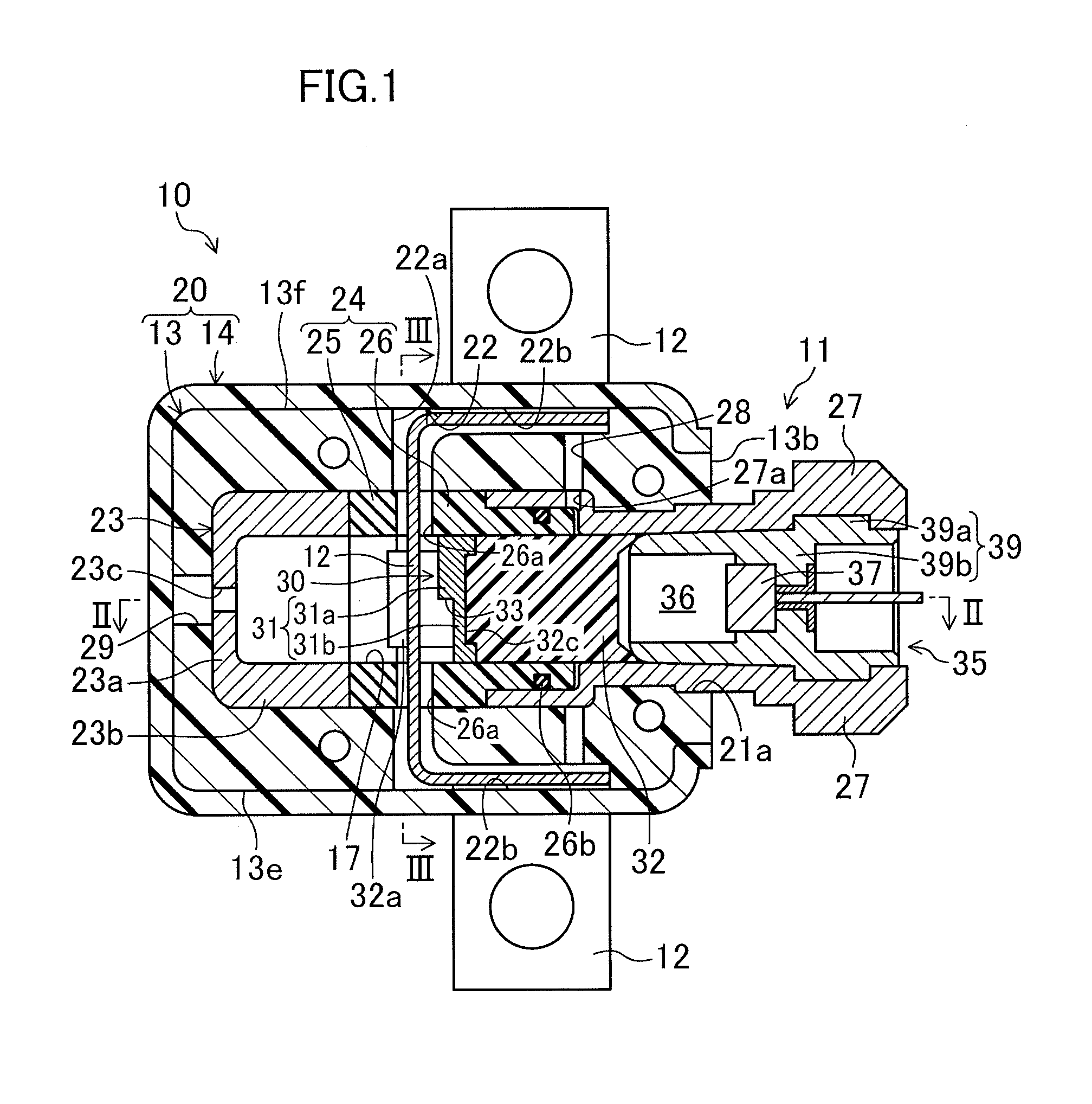
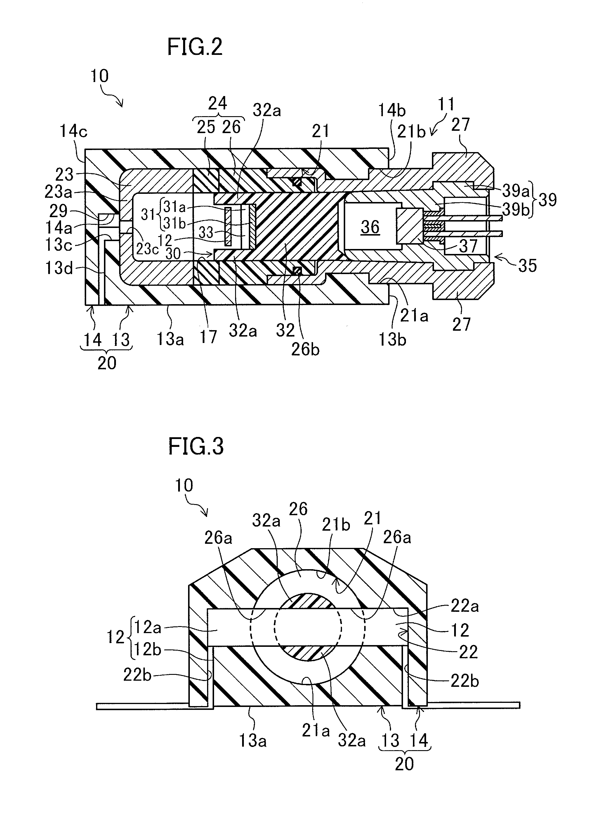
[0062]Specifically, the cutter (10) includes a case (11) as illustrated in FIG. 1 and FIG. 5, and a stopper (23), an inner cylinder (24), a blade (30), and a gas generator (35) are accommodated in the case (11). The case (11) comprises a case member of the present invention.
[0063]For convenience of explanation, the left-hand side of FIG. 2 is hereinafter referred to as the “front side,” the right-hand side of FIG. 2 is hereinafter referred to as the “back side,” the upper side of FIG. 2 is hereinafter referred to as the “upper side,” and the lower side of FIG. 2 is hereinafter referre...
second embodiment
of the Invention
[0116]Now, the second embodiment will be described. As shown in FIG. 13, the second embodiment is directed to a breaker (50) including a cutter (10) of the present invention. The breaker (50) includes a load terminal (55) and a line terminal (54) provided on the resin casing (not shown), and a terminal-to-terminal connection member (51) which is a harness (12) configured to connect the load terminal (55) and the line terminal (54).
[0117]The terminal-to-terminal connection member (51) includes a stationary contact (52) connected to the load terminal (55), and a movable contact (53) connected to the line terminal (54). The movable contact (53) is movable between the contact location at which the movable contact (53) is in contact with the stationary contact (52) and a noncontact location at which the movable contact (53) is apart from the stationary contact (52). When the movable contact (53) moves to the contact location, a movable contact point (53a) of the movable c...
third embodiment
of the Invention
[0124]Now, the third embodiment will be described. As shown in FIG. 14, the third embodiment is directed to a contactor including a cutter (10) according to the present invention. As shown in FIG. 14, the contactor (70) includes a load terminal (75) and a line terminal (74) provided on a resin casing (86), and a terminal-to-terminal connection member (71) which is a harness (12) configured to connect the load terminal (75) and the line terminal (74).
[0125]The terminal-to-terminal connection member (71) includes a first stationary contact (68) connected to the load terminal (75), a second stationary contact (69) connected to the line terminal (74), and a movable contact (73) coupled to a movable core (81) described below. The movable contact (73) is movable between the contact location at which the movable contact (73) is in contact with a pair of stationary contacts (68, 69) and a noncontact location at which the movable contact (73) is apart from the pair of station...
PUM
| Property | Measurement | Unit |
|---|---|---|
| Thickness | aaaaa | aaaaa |
| Pressure | aaaaa | aaaaa |
| Flexibility | aaaaa | aaaaa |
Abstract
Description
Claims
Application Information