Hydraulic tool having interchangeable heads

Inactive Publication Date: 2013-10-10
CIOTTI ARMAND E
View PDF11 Cites 25 Cited by
  • Summary
  • Abstract
  • Description
  • Claims
  • Application Information

AI Technical Summary

Benefits of technology

[0008]This invention addresses the problem of interchanging heads on a hydraulic tool and at the same time making the

Problems solved by technology

Nevertheless, tools utilizing a common power unit and interchangeable heads have not been made ava

Method used


Image

  • Hydraulic tool having interchangeable heads
  • Hydraulic tool having interchangeable heads
  • Hydraulic tool having interchangeable heads

Examples


Embodiment Construction

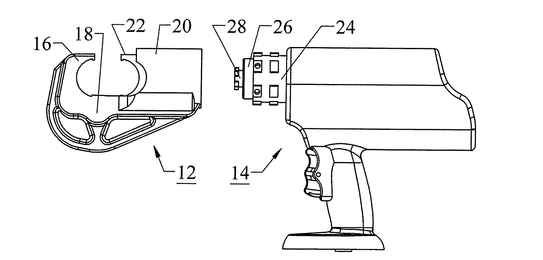
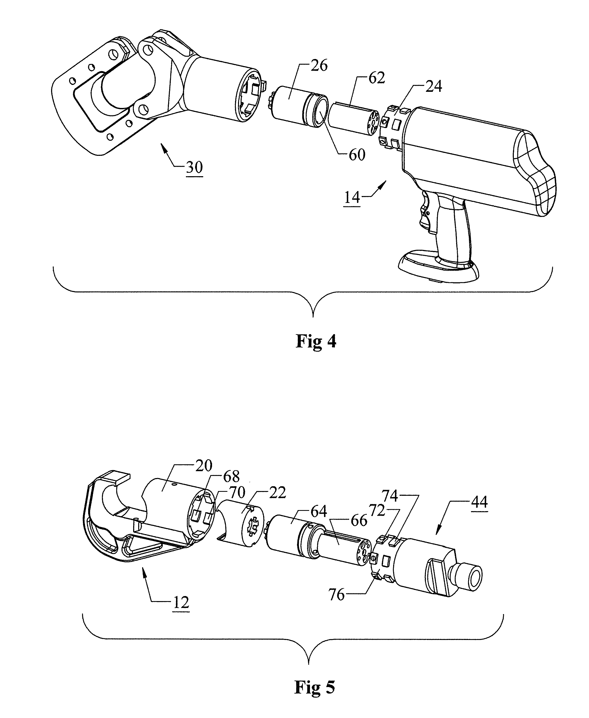
[0028]The tool according to the invention comprises two basic components, a head and a power unit. The head and the power unit can be disconnected from each other so that the head can be interchanged with other heads for different purposes, all usable with the same power unit, and so that particular head can be used with any of several different power units, e.g., a battery-operated power unit, a power unit operated from a remote hydraulic fluid supply, or a hand-operated power unit.

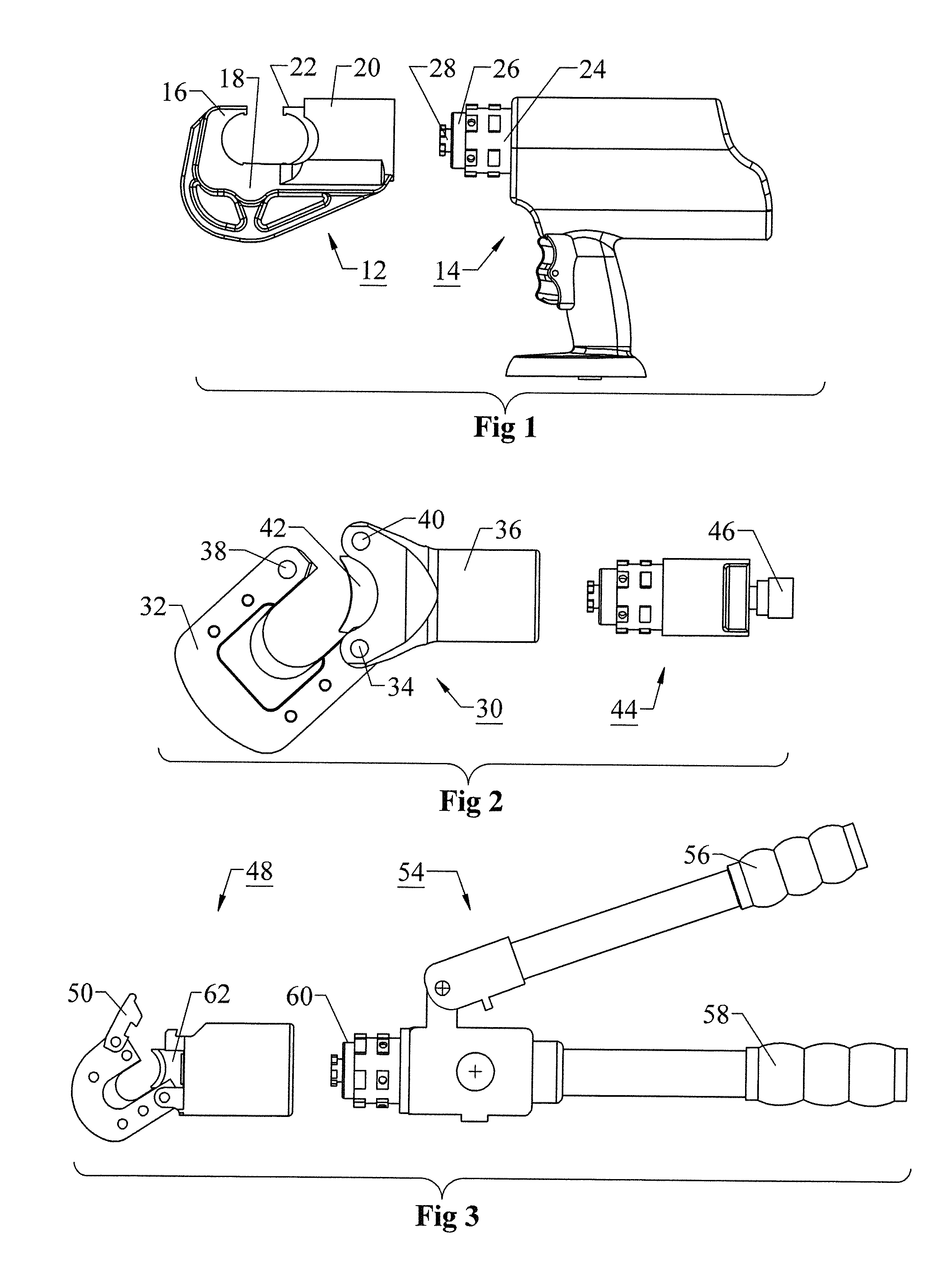
[0029]FIGS. 1, 2 and 3 show three of many possible combinations of a head and a power unit. In FIG. 1, a crimping head 12 is combined with a hand-held battery-operated power unit 14. The crimping head includes a concave anvil 16 rigidly connected by a reinforced bridge 18 to a hollow receiver 20 in which a movable member 22 is guided for sliding movement toward and away from the anvil 16. An opening is provided opposite the bridge for entry of a tubular connector for crimping. The movable member 22 has a...


PUM

PropertyMeasurementUnit
Lengthaaaaaaaaaa
Forceaaaaaaaaaa
Pressureaaaaaaaaaa

Abstract

In a hydraulic tool such as a crimping or cutting tool used by electric utility workers, interchangeability of heads and interchangeability of power units is afforded by connecting a cylinder on the power unit to a receiver on the head. Interlocking lugs allow the head to be secured to the power unit at any selected one of a plurality of rotational positions. A piston and a movable die in the head also have interlocking lugs. To enable the lugs on the piston and movable die to engage simultaneously with the engagement of the lugs on the cylinder and receiver, the piston is secured against rotation by a slotted guide the slots of which receive inwardly protruding pins fixed to the piston. For increased versatility, plural pressure relief valves can be selected by means of a manual selection valve to set the maximum force exerted by the tool.

Description

FIELD OF THE INVENTION[0001]This invention relates to hydraulic tools of the kind used by electric utility workers to cut, crimp, or spear cables. It relates more particularly to a hydraulic tool, comprising a power unit and a working head, in which the working head can be interchanged with other working heads, so that the power unit can be used with any of various heads, or so that a given working head can be used with any of several different power units.BACKGROUND OF THE INVENTION[0002]In the installation and maintenance of electric power cables it is common practice to connect lengths of conductor by inserting ends of the conductors into a tubular metal connector, which is then crimped onto the conductors to connect them together permanently. Because spans of cable are typically quite heavy, the connectors must be strong enough to sustain the high tensile forces, and are therefore necessarily resistant to deformation. It follows that large crimping forces, typically 6 tons or mo...

Claims


Application Information

Patent Timeline
IPC IPC(8): B25F3/00B25F1/02
CPCB25F5/005B25F3/00B25B27/10B25B27/146Y10T29/53226B25B27/14
Inventor CIOTTI, ARMAND
Owner CIOTTI ARMAND E
Why Eureka
Try Eureka