Computer generated hologram type display device

Active Publication Date: 2013-10-10
PANASONIC INTELLECTUAL PROPERTY MANAGEMENT CO LTD
View PDF2 Cites 30 Cited by
  • Summary
  • Abstract
  • Description
  • Claims
  • Application Information

AI Technical Summary

Benefits of technology

[0029]According to an aspect of the present application, a CGH type display device, which c

Problems solved by technology

One of the problems of the CGH method is the computing volume of a diffraction pattern.
However, in a case where a diffraction pattern is computed by inverse Fourier transform and the like, in order to reduce computation volume, it becomes difficult to freely set a position of a reconstructed image (distance from the liquid crystal panel) by CGH, since approximation is used for computing the distance between the object (original image) and the liquid crystal panel.
Another problem of a CGH type display device is quantization noise.
In improving the image quality in a CGH type display device however, there is a problem that it becomes difficult to improve the image quality of the entire reconstructed image.
However, distortion is generated at the edges of the screen,

Method used


Image

  • Computer generated hologram type display device
  • Computer generated hologram type display device
  • Computer generated hologram type display device

Examples


embodiment 1

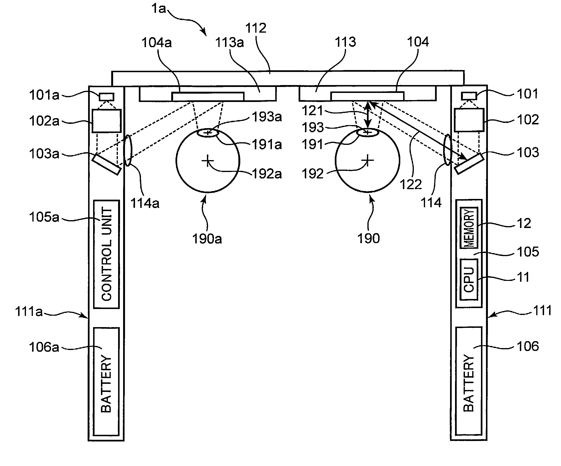
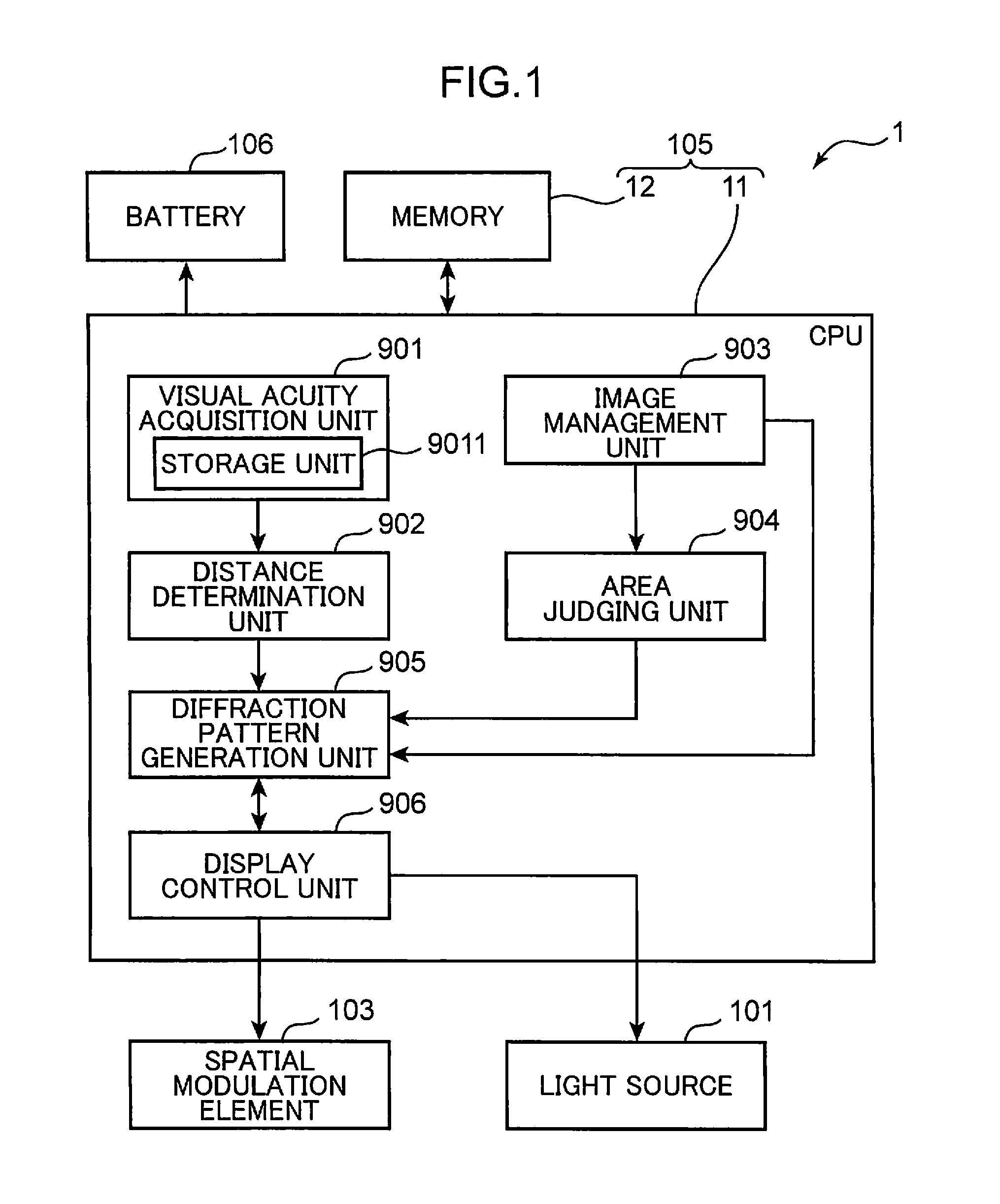
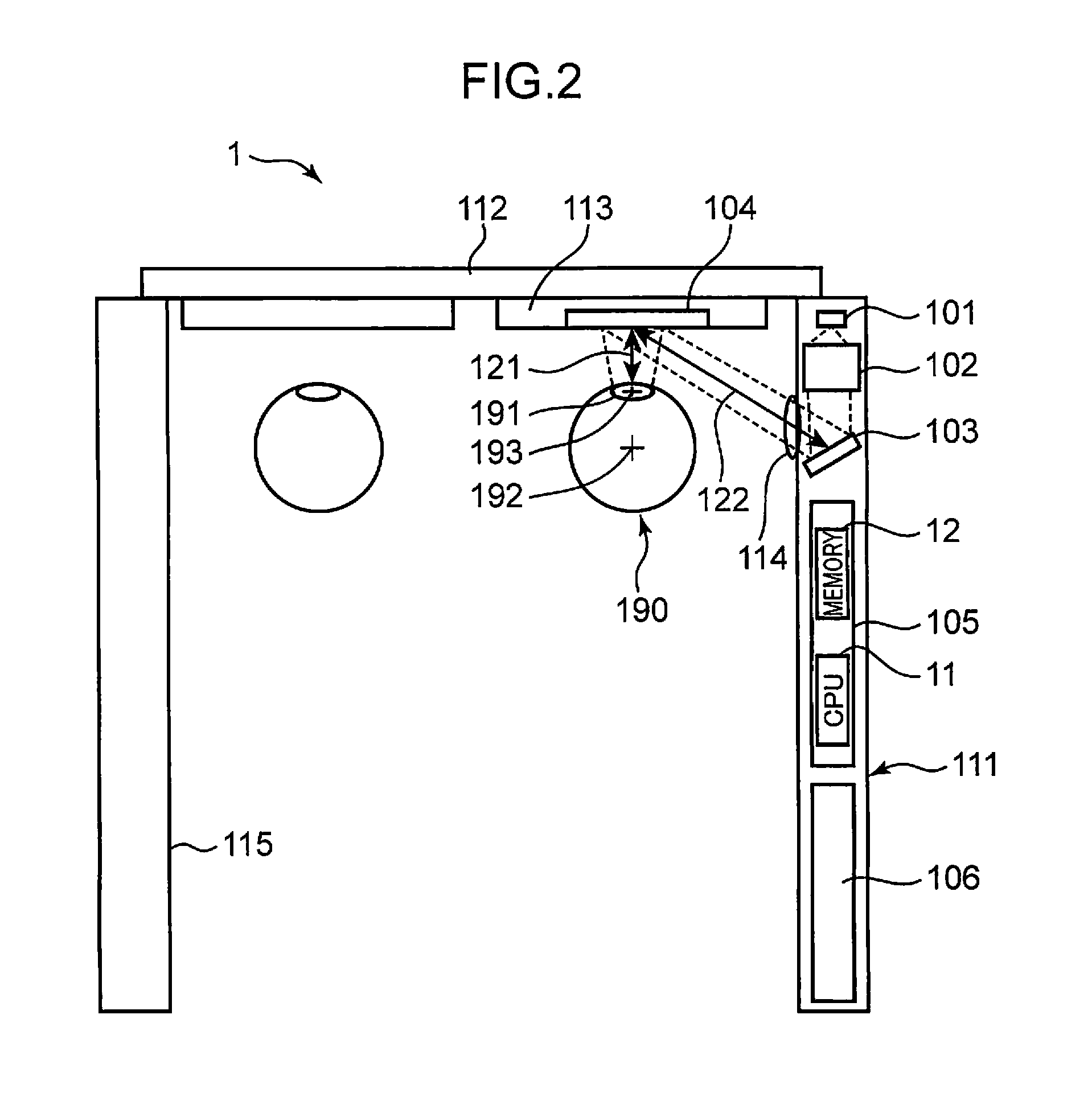
[0069]FIG. 1 is a functional block diagram of a head-mounted display device (HMD) 1 according to Embodiment 1. FIG. 2 is a schematic diagram depicting a configuration of the display device 1 shown in FIG. 1. As shown in FIG. 2, the display device 1 of Embodiment 1 has a shape like spectacles, and FIG. 2 is a top view. The configuration of the display device 1 according to Embodiment 1 will now be described with reference to FIG. 1 and FIG. 2.

[0070]A light source 101 is a laser light source that outputs laser light. In Embodiment 1, a semiconductor laser (laser diode) that outputs laser light having a green wavelength is used as the light source 101. As the light source 101, a single color of red or blue may be used instead, or three colors of red, green and blue may be multiplexed for color display, or the three colors of red, green and blue may be driven by time-division driving to implement color display. As the light source 101, a laser other than a semiconductor laser may be use...

embodiment 2

[0137]Embodiment 2 shows an example of control to suppress noise that is generated when a fictive image is displayed, depending on the content of the display. In Embodiment 2, a composing element the same as or similar to that of Embodiment 1 is denoted with a same or similar reference symbol.

[0138]FIG. 12 is a functional block diagram of a display device 1B according to Embodiment 2. The configuration of the head-mounted display device (HMD) 1B according to Embodiment 2 is similar to that of Embodiment 1 shown in FIG. 2, therefore description is omitted. A function of each functional block in FIG. 12 will be described later.

[0139]The differences of the display device 1B from the display device 1 shown in FIG. 1 are that a spatial modulation element 103B is included instead of the spatial modulation element 103, and a control unit 105B is included instead of the control unit 105. The control unit 105B includes a CPU 11B and a memory 12B. As functional blocks, the CPU 11B includes an...

embodiment 3

[0169]Embodiment 3 shows an example of control to display a fictive image having a wide viewing angle, by changing the diffracted light used for display depending on the position of the fictive image to be displayed to the user. In Embodiment 3, a composing element the same as or similar to that of Embodiment 1 is denoted with a same or similar reference symbol.

[0170]FIG. 16 is a functional block diagram of a display device 1C according to Embodiment 3. FIG. 17 shows a configuration of the display device 1C according to Embodiment 3. Description on a composing element the same as that of Embodiment 1 is omitted.

[0171]The differences of the display device 1C from the display device 1 shown in FIG. 1 are that a control unit 105C is included instead of the control unit 105, and a shielding unit 108 is further included. The control unit 105C includes a CPU 11C and a memory 12C. As functional blocks, the CPU 11C includes an image management unit 903, a diffraction pattern generation unit...


PUM


Abstract

A display device includes: a light source; an illumination optical system; a diffraction pattern generation unit; a spatial modulation element that generates diffracted light; and a shielding unit that selectively enters a first state where a first and second partial areas are a transmitting and shielding areas, respectively, and a second state where the first and second partial areas are the shielding and transmitting areas, respectively. The spatial modulation element displays the fictive image on a first and second display areas corresponding to the first and second partial areas when the shielding unit is in the first and second states, respectively. The diffraction pattern generation unit generates a first and second portion diffraction patterns from an image in an area corresponding to the first and second display areas out of the original image when the shielding unit is in the first and second states, respectively.

Description

CROSS-REFERENCE TO RELATED APPLICATIONS[0001]This application claims the benefit of priority to Japanese Patent application No. 2012-088972 filed on Apr. 10, 2012, the entire content of which is hereby incorporated herein by reference.TECHNICAL FIELD[0002]The present application relates to a display device, such as a head-mounted display, which displays information by diffracting laser light using a diffraction pattern generated by a computer generated hologram.BACKGROUND ART[0003]A head-mounted display (hereafter “HMD”) is a device that displays information to a user in a state of being mounted on the head of the user. In terms of mounting on the head, generally it is preferable that the HMD is compact and light, but in terms of display performance, it is preferable that the screen is large and image quality is high. In conventional HMDs, there is a method of optically magnifying an image displayed on a compact liquid crystal panel or the like using a convex lens, a free-form surfa...

Claims


Application Information

Patent Timeline
IPC IPC(8): G02B27/01
CPCG02B27/0172G02B27/0103G02B2027/014G02B2027/011G02B27/017
Inventor SUGIYAMA, KEIJIKASAZUMI, KENICHI
Owner PANASONIC INTELLECTUAL PROPERTY MANAGEMENT CO LTD
Why Eureka
Try Eureka