Lighting device and method for manufacturing a lighting device

a technology of lighting device and lighting device, which is applied in the direction of color-music apparatus, light source combination, instruments, etc., can solve the problems of not providing sufficient energy-saving functional lighting, not providing the same various designs of eco-friendly lamps, etc., and achieves the effect of relatively simple lighting device technology

Active Publication Date: 2013-10-10
SIGNIFY HLDG BV
View PDF7 Cites 54 Cited by
  • Summary
  • Abstract
  • Description
  • Claims
  • Application Information

AI Technical Summary

Benefits of technology

[0016]In an embodiment of the present invention, at least one of the second light emitting element and the first light emitting element may be dimmable, which is advantageous in that it provides a step-less transition between the two above-mentioned operation modes of the lighting device. Moreover, the first light emitting element and the second light emitting element may be simultaneously and/or separately (individually) dimmed. For example, when the light intensity of the first light emitting element is increased, simultaneously, also the light intensity of the second light emitting element may be increased. Such a kind of regulation may be implemented using a single dimming device common to all light emitting elements (making the lighting device relatively technically simple). Hence, when both the first light emitting element and the second light emitting element are operated at a low dimmed level (i.e. at a low light intensity) the total light-output

Problems solved by technology

Such conventional eco-friendly lamps do not provide the same various designs as traditional incandescent light bulbs.
A drawback with such a li

Method used


Image

  • Lighting device and method for manufacturing a lighting device
  • Lighting device and method for manufacturing a lighting device
  • Lighting device and method for manufacturing a lighting device

Examples


Embodiment Construction

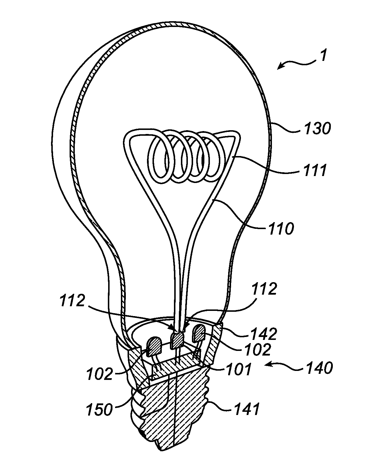
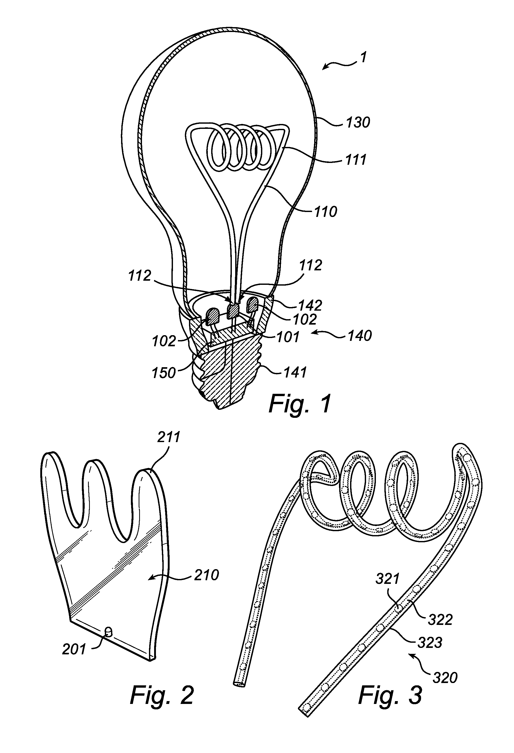
[0033]With reference to FIG. 1, there is shown a lighting device in accordance with an embodiment of the present invention.

[0034]FIG. 1 shows a lighting device 1 comprising a first light emitting element 101 and a second light emitting element 102. The first light emitting element 101 is optically coupled to a light guide 110 having an out-coupling surface 111. The optical coupling can be provided e.g. via an optical element (not shown) arranged between the first light emitting element 101 and the light guide 110 or by linking the first light emitting element 101 directly to the light guide 110, as shown in FIG. 1.

[0035]Optionally, the lighting device may be provided with additional first light emitting elements being optically coupled to the light guide 110. For example, one first light emitting element may be coupled to a first end of the light guide 110 and another first light emitting element may be coupled to another end of the light guide 110 (opposite to the first end).

[0036]...


PUM


Abstract

The invention relates to a lighting device and a method of manufacturing such a lighting device. The lighting device (1) comprises a first light emitting element (101) being optically coupled to a light guide (110) having an out-coupling surface (111) for illumination via the light guide. Further, the lighting device comprises a second light emitting element (102) dedicated for direct illumination from the lighting device. The invention is advantageous in that the lighting device provides both a decorative look and a functional illumination, and is still energy-efficient since the light emitted from the second light emitting element is directly emitted from the light emitting element without unnecessary energy-loss.

Description

FIELD OF THE INVENTION[0001]The present invention generally relates to the field of lighting devices.BACKGROUND OF THE INVENTION[0002]Traditional incandescent light bulbs are available in various designs such as plain functional bulbs with different glass finishes (e.g. transparent, diffuse or colored) and decorative bulbs with complex filaments, wherein the filament itself serves a decorative purpose. However, due to demands on power saving in lighting devices, driven by eco awareness and legislation, traditional incandescent light bulbs are being replaced by more power efficient light sources such as fluorescent lamps and LED (light emitting diode) lamps. Such conventional eco-friendly lamps do not provide the same various designs as traditional incandescent light bulbs.[0003]A solution of how to provide a lighting device resembling a carbon filament lamp is disclosed in WO 2006 / 035349. The document shows a lighting device comprising a solid state light source optically coupled to...

Claims


Application Information

Patent Timeline
IPC IPC(8): F21K99/00F21Y113/20
CPCF21K9/52F21W2121/00F21K9/135F21Y2113/005F21Y2113/02F21Y2101/02F21V23/003F21K9/232F21Y2115/10F21Y2113/13F21K9/238F21Y2103/10F21Y2107/00F21Y2107/70H05K1/189F21S4/26H05K1/028H05K2201/051H05K2201/10113H05K2201/10106F21K9/61F21K99/00F21S10/005F21Y2113/20G02B6/0021G02B6/001
Inventor KWISTHOUT, CORNELIS WILHELMUS
Owner SIGNIFY HLDG BV
Why Eureka
Try Eureka