
Method of forming a composite structure comprising a flange

Active Publication Date: 2013-10-10
GKN AEROSPACE SERVICES LTD
View PDF6 Cites 26 Cited by
  • Summary
  • Abstract
  • Description
  • Claims
  • Application Information

AI Technical Summary

Benefits of technology

The present invention relates to a method for producing a composite structure with improved flexibility and stiffness. The method involves creating two bends in a preform and keeping the plies in tension along their length to prevent distortion. The composite structure includes a lip portion which improves stiffness and rigidity. The method has improved flexibility and stiffness of the composite structure.

Problems solved by technology

It has proved difficult to use a machine to lay-up the plies of the composite material of the flange and to integrate the composite material of the flange with the composite material of the housing, before the housing and the flange are cured.
This tends to produce a flange of inconsistent quality and, in order to compensate for this, a flange which is heavier than it needs to be because it is using an excess of composite material.

Method used


Image

  • Method of forming a composite structure comprising a flange
  • Method of forming a composite structure comprising a flange
  • Method of forming a composite structure comprising a flange

Examples


Embodiment Construction

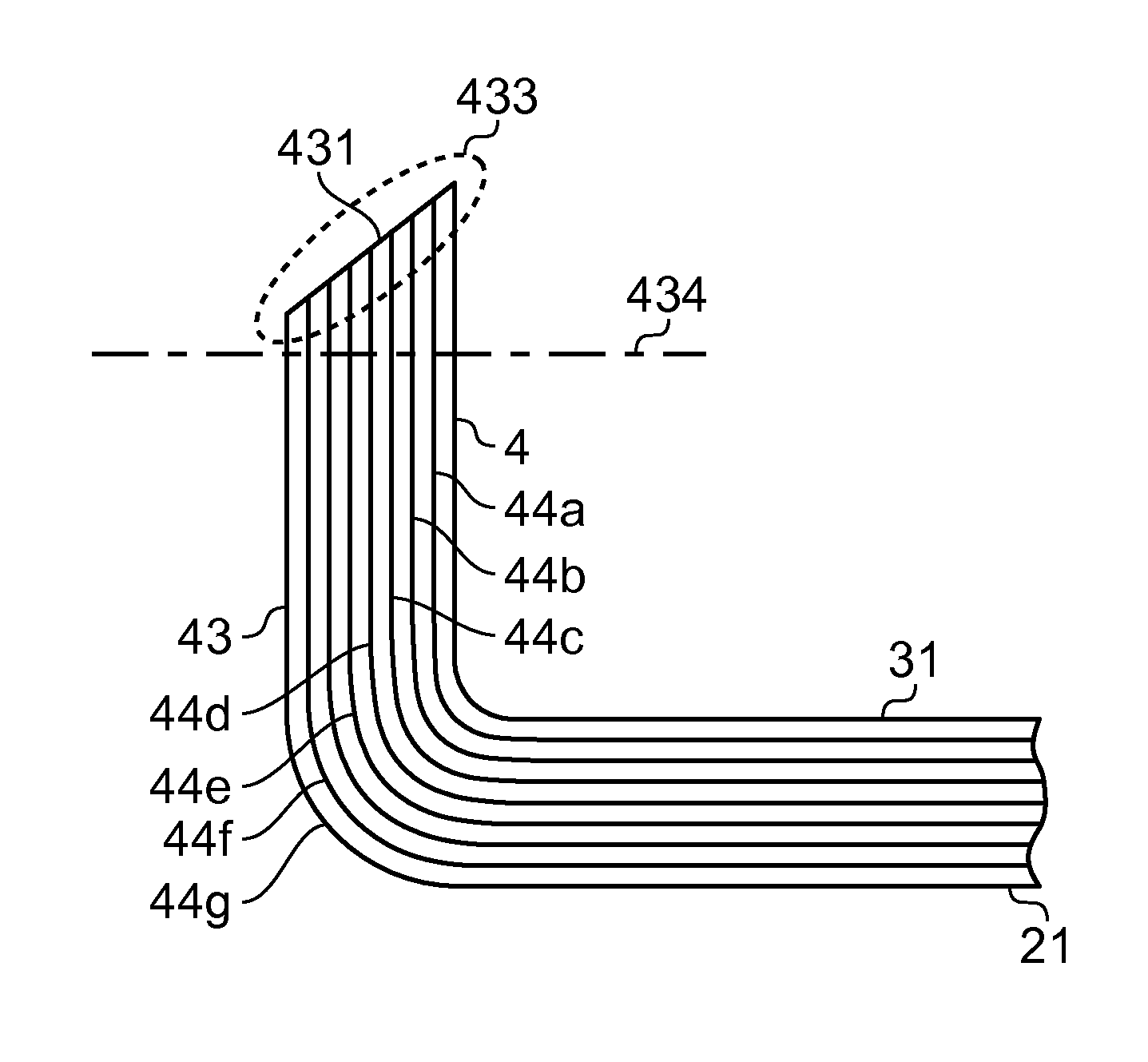
[0079]Embodiments of the present invention will be described with reference to FIGS. 9 to 14 which illustrate how the method of the present invention builds on our existing method already described above with reference to FIGS. 3 to 8.

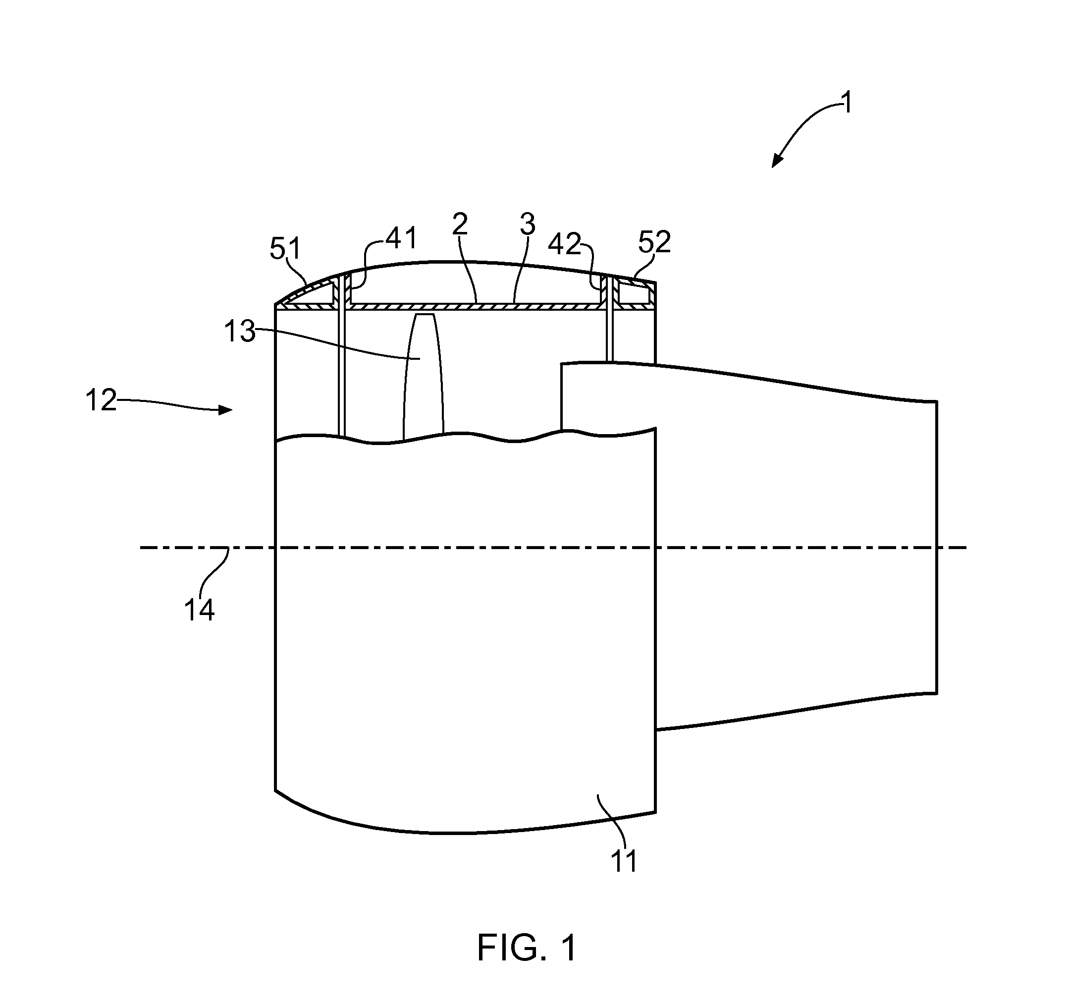
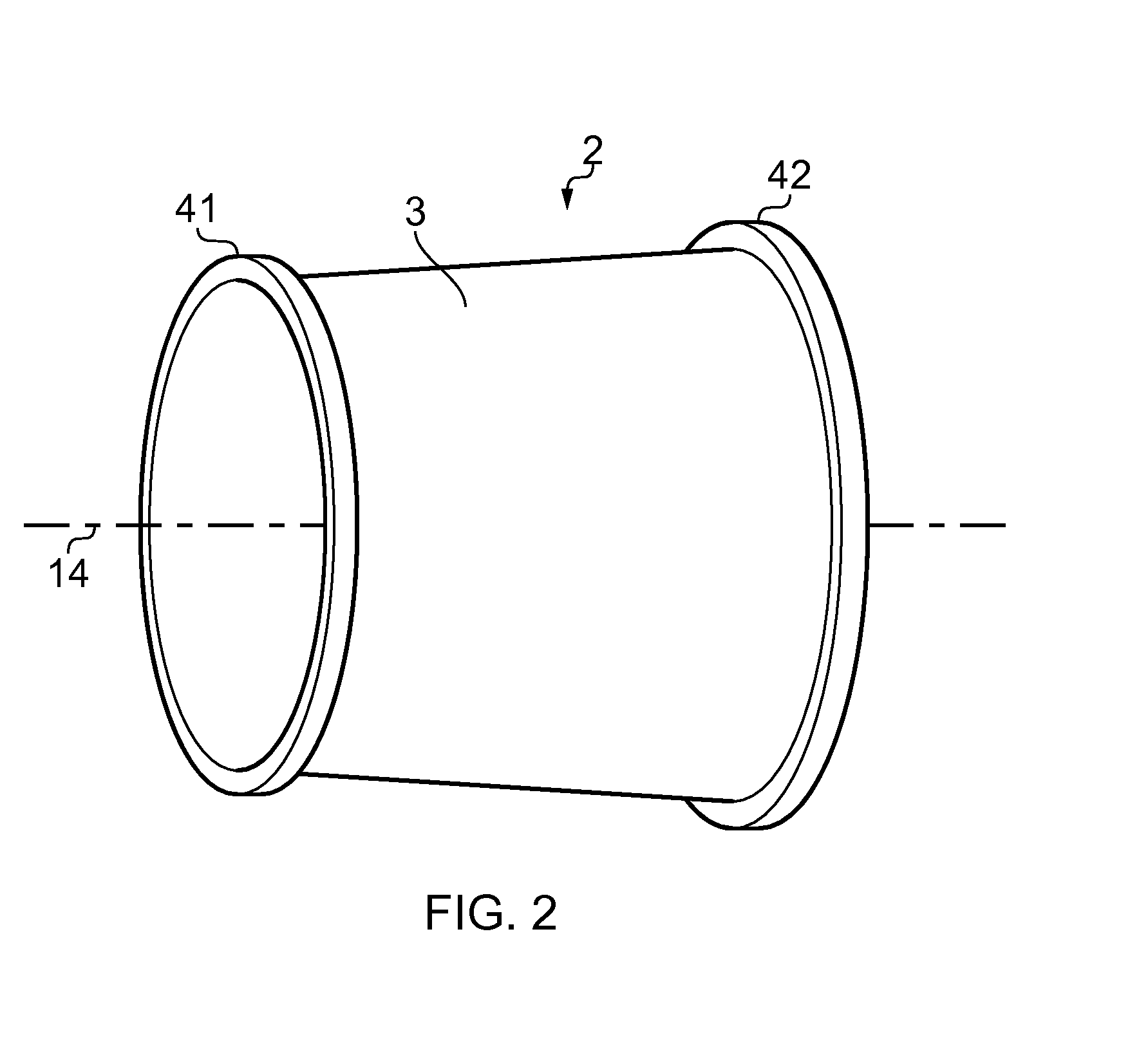
[0080]As shown in FIG. 9, the mould 6 of the experimental tool of FIGS. 3 to 6 is modified by the addition of a second mould portion in the form of an end plate 65 which is positioned adjacent the movable blocks 62 (the movable mould portions). The main or first part 61 of the mould (the first mould portion) is fixed to the end plate 65 (the second mould portion) so that both the first and second mould portions 61, 65 are fixed or static relative to the movable blocks 62. The mould surface 651 of the end plate 65 combines with the mould surface 611 of the first part 61 and the mould surfaces 621 of the movable blocks 62 to form an overall mould surface which is a curved part of a generally-cylindrical mould surface, and a preform 7 is laid-up on the mo...


PUM

PropertyMeasurementUnit
Temperatureaaaaaaaaaa
Angleaaaaaaaaaa
Structureaaaaaaaaaa

Abstract

Method forming a composite structure (9) comprising a main body and a flange. The composite structure is manufactured by laying-up a preform (7) on a mould (6). The preform (7) does not have the first and second bends and comprises a first part which corresponds to the main body of the composite structure and a second part which corresponds to the flange of the composite structure. The second part of the (preform (7) has a proximal portion which corresponds to the wall portion of the flange and a distal portion which corresponds to the lip portion of the flange. The preform (7) comprises a plurality of plies and uni-directional ply material extends from the first part of the preform (7) to the distal portion of the second part of the preform (7). The flange is formed by advancing movable portion(s) (62) of the mould 6 to form the proximal portion of the second part of the preform (7) to create the first bend (81) and by forming the distal portion of the second part of the preform (7) around the advancing movable portion(s) (62) of the mould (6) to create the second bend (83). The presence of the two bends (81, 83) ensures that the ply material (78) is kept in tension during the forming operation.

Description

FIELD OF THE INVENTION[0001]The present invention relates to a composite structure such as a containment case for a gas turbine engine, although the present invention is broadly applicable to composite structures such as, in the aerospace industry, a wing spar or any component that needs to include an integral flange such as a straight flange or a curved flange such as an annular flange.BACKGROUND[0002]Characteristics of composite materials have meant that composite components are employed in an increasing range of applications from aerospace to automotive parts.[0003]In the aerospace industry, for example, composite materials have been used for a number of years owing to their strength to weight ratio. The term “composite materials” (known also as “composites”) is used to describe materials comprising for example glass fibre or carbon fibres and an epoxy resin (or similar). These are also known as glass reinforced plastic or carbon fibre reinforced composites. The carbon fibre rein...

Claims


Application Information

Patent Timeline
IPC IPC(8): B32B37/02
CPCB29C53/04B29C57/00B29C70/342B29C70/345B29K2105/0881B29L2009/00Y10T156/1044F01D21/045F01D25/24F05D2300/603B32B37/02Y02T50/672Y10T428/24628B29L2031/30Y02T50/60B29C57/04B29C70/30B29C70/443B29C70/56F01D21/04F01D25/243
Inventor MORAM, JONATHAN PAULMARENGO, GIOVANNI ANTONIOMACLEAN, DAVID JAMESRALFS, BENWILES, GARYGAWN, MARCUS JASON
Owner GKN AEROSPACE SERVICES LTD
Features
  • Generate Ideas
  • Intellectual Property
  • Life Sciences
  • Materials
  • Tech Scout
  • Unparalleled Data Quality
  • Higher Quality Content
  • 60% Fewer Hallucinations
Learn More