Portable fluid warmer

a fluid heating device and portable technology, applied in the direction of exothermal chemical reaction heat production, contraceptive devices, light and heating apparatus, etc., can solve the problems of patient core temperature dropping to dangerous levels, large and cumbersome devices, and not convenient to use, so as to slow or prevent the complete chemical reaction from occurring, the effect of enhancing the rapid flow of crystallising liquid chemical and enhancing the speed of the crystallising liquid chemical

Inactive Publication Date: 2013-10-10
FBE
View PDF14 Cites 9 Cited by
  • Summary
  • Abstract
  • Description
  • Claims
  • Application Information

AI Technical Summary

Benefits of technology

[0020]The inventors have discovered that the reaction can be accelerated by introducing the reactive liquid into a reaction chamber that is at least partially evacuated of air, and that contains a trigger such as crystals or particulate matter or any other means that induces the reactive liquid to crystallise. The rapid movement of reactive liquid with respect to the trigger that initialises or promotes crystallization, enables the growing crystals (solidification) to break and spread throughout the reactive liquid without being localized in one part of the reaction chamber that may cause blockages.
[0037]The tubing extending through the reaction chamber may be of any suitable configuration that maximises the heat transfer from the exothermic reaction to the infusion or transfusion fluid to be warmed within the tubing.

Problems solved by technology

Blood for transfusions is typically stored at approximately 4° C. Prior to patient transfusions, it is preferable that the blood be warmed to a temperature substantially the same as that of the living body, approximately 37° C. Failure to warm the blood prior to transfusion, may result in the patient's core temperature dropping to dangerous levels potentially resulting in hypothermia.
These are typically large and cumbersome devices that draw power from a mains supply.
These types of devices, whilst satisfactory in hospital or clinical situations where a constant source of power is available, are not convenient to use in situations that are remote from reliable power sources or in remote locations where it is not practical to carry such large and cumbersome equipment, such as when a patient is moved between wards or geographical locations.
There are however a number of problems with batteries including that they are heavy, bulky and require replacement or recharging at regular intervals.
Given that heating equipment places substantial load on the batteries, it is not possible for these batteries to be small.
Additionally, the maintenance issues associated with batteries are such that, for example, if the portable blood warmer is used in an emergency vehicle then it is necessary that regular checks are made on the condition of the battery or indeed that spare batteries are available such that there is always a source of power available.
Furthermore, the requirement of batteries in order to operate the blood warmer dramatically increases the overall weight of the apparatus and therefore if rescue workers are required to trek into a remote location this then places an additional burden on them and may complicate matters if the unit fails to operate due to problems associated with the power source.
One potential problem of using chemical reaction described in the prior art to generate the required heat, is the challenge of controlling and regulating the heat generated by the chemical reaction, which otherwise has the potential to damage the blood or infusion fluids if the temperature is raised too high.
However a difficulty in using these types of chemical reagents in currently available devices is that the flow of chemical liquid and crystals through the reaction chamber may be too slow.
In addition the flow is further hampered by the crystallisation of the reagents that may result in blockages occurring within the reaction chamber.
If this occurs the device may not be ideal in an emergency situation where the biological fluid warmer should preferably be fast acting, otherwise particularly in emergency situations the health of the patient may be compromised.

Method used


Image

  • Portable fluid warmer
  • Portable fluid warmer
  • Portable fluid warmer

Examples


Embodiment Construction

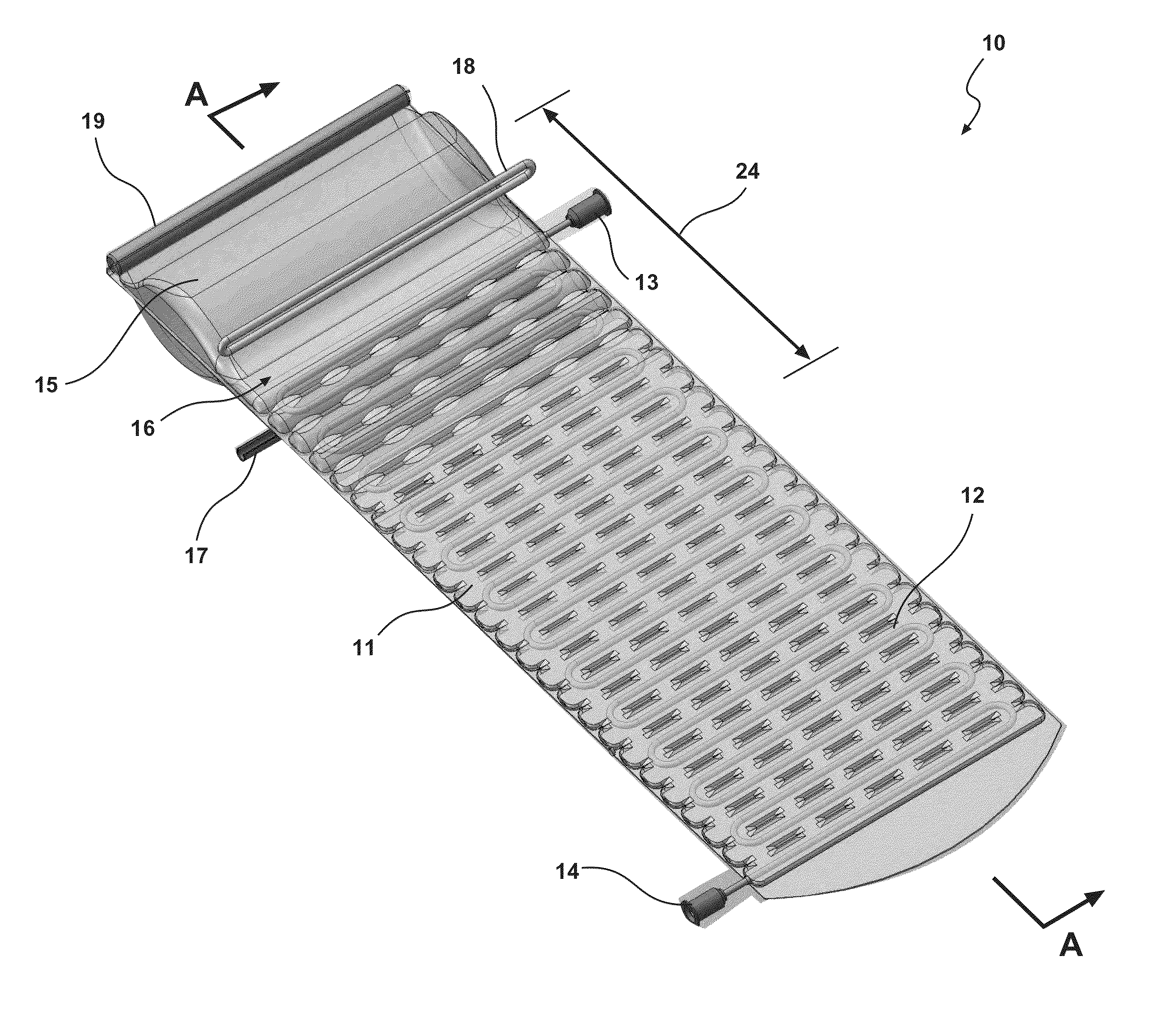
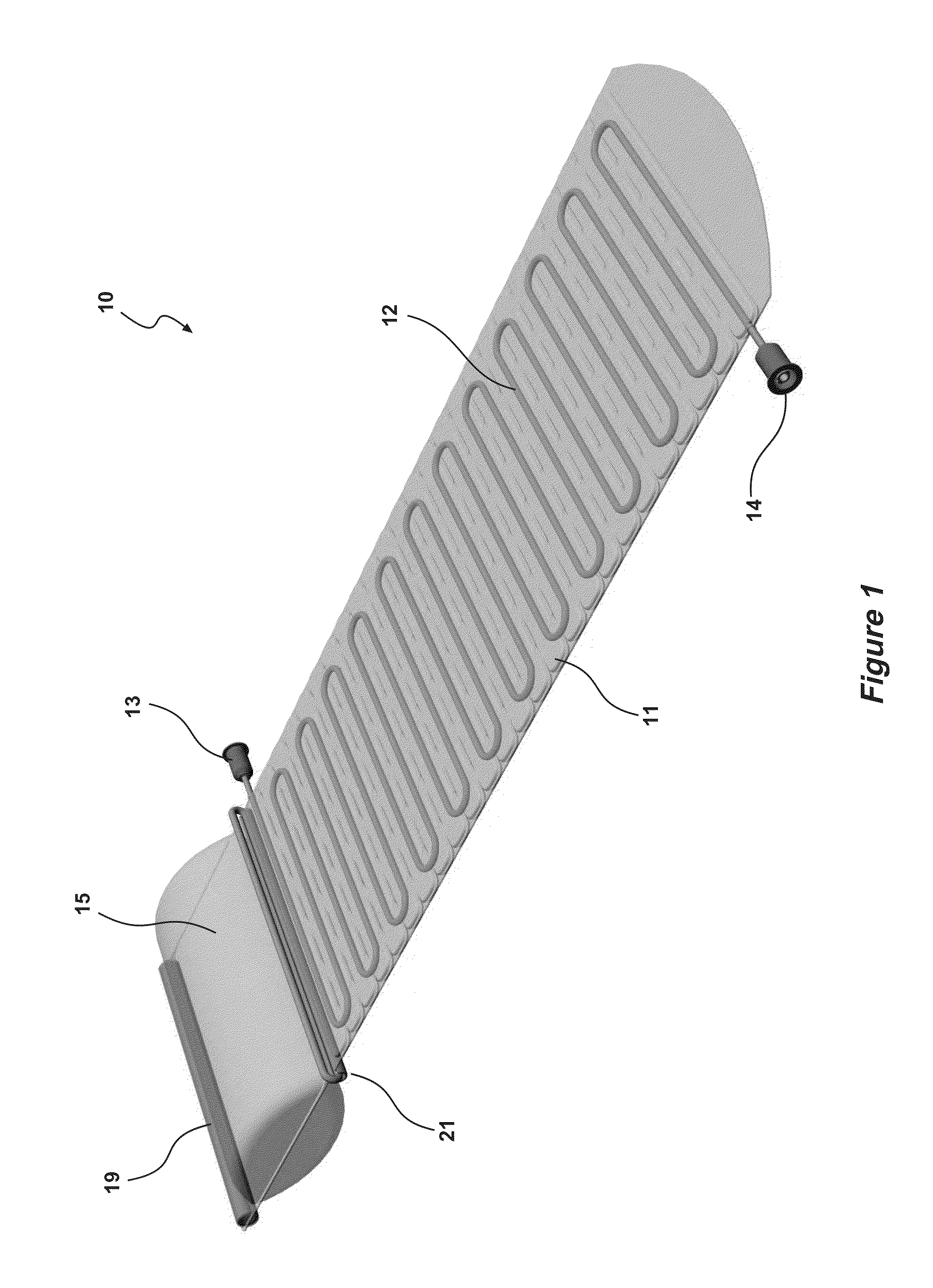
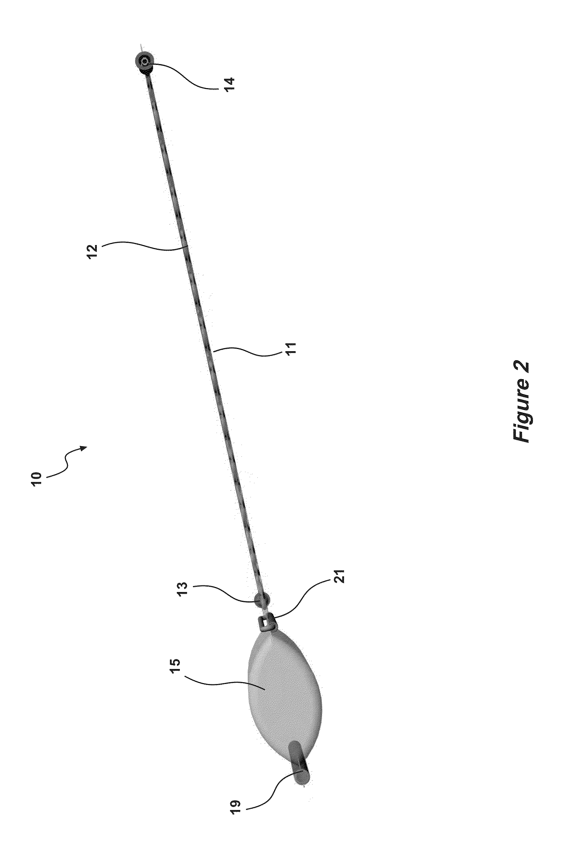
[0054]Turning to the figures for a detailed explanation of the invention, there is illustrated a fluid heating device demonstrating by way of examples arrangements in which the principles of the present invention may be employed. FIG. 1 illustrates an embodiment of the device (10) of the present invention including a reaction chamber (11) for containing the exothermic reaction. This reaction chamber further contains the tubing (12) in a planar serpentine arrangement through which the infusion or transfusion fluid to be warmed can pass between inlet (14) and outlet (13). As illustrated in FIG. 2 the reaction chamber (11) has a generally envelope shaped configuration.

[0055]The reaction chamber (11) is connected to a secondary chamber (15) that contains a reactive liquid compound needed for the exothermic reaction. Prior to use the reactive liquid in the secondary chamber (15) cannot enter the reaction chamber because the two chambers are separated by way of a clamp (21), comprising a ...


PUM


Abstract

A device (10) for warming infusion or transfusion fluids by an exothermic reaction of a reactive liquid, including at least one reaction chamber (11) containing a trigger, and a passageway (12) extending through said reaction chamber (11) for movement of said infusion or transfusion fluids therethrough, wherein the reactive liquid is introduced into said reaction chamber (11), being at least partially evacuated of air, to thereby initiate said exothermic reaction.

Description

CROSS REFERENCE TO RELATED APPLICATION[0001]This application is a national stage entry of PCT / AU2011 / 001369 filed Oct. 27, 2011, under the International Convention claiming priority over Australian Patent Application No. 2010904779 filed Oct. 27, 2010.FIELD OF THE INVENTION[0002]The present invention relates to a compact, self-contained fluid heating device. In particular, the invention relates to devices for heating fluids such as blood that can be used in remote locations.BACKGROUND OF THE INVENTION[0003]Blood for transfusions is typically stored at approximately 4° C. Prior to patient transfusions, it is preferable that the blood be warmed to a temperature substantially the same as that of the living body, approximately 37° C. Failure to warm the blood prior to transfusion, may result in the patient's core temperature dropping to dangerous levels potentially resulting in hypothermia.[0004]There currently exists a number of portable blood warming devices used in hospitals. These a...

Claims


Application Information

Patent Timeline
Patent Type & Authority Applications(United States)
IPC IPC(8): A61M5/44F24V30/00
CPCA61M5/44A61M5/445A61M2205/364F24J1/00F24V30/00
Inventor ROBSON, JOHNMCEWEN, MARKWOOLFORD, ROBINROXBY, DAVID
Owner FBE
Why Eureka
Try Eureka