Wall lifting, transport and positioning device with roller pins

a technology of roller pins and positioning devices, which is applied in the direction of lifting devices, building materials handling, construction, etc., can solve the problems of large number of workers required to erect, position, and save significant onsite construction time and labor

Inactive Publication Date: 2013-10-17
HOVENIER FRED E +1
View PDF3 Cites 30 Cited by
  • Summary
  • Abstract
  • Description
  • Claims
  • Application Information

AI Technical Summary

Benefits of technology

[0011]According to an aspect of the invention, there is provided a wall lifting, transport and positioning device for use with a wall section upon a worksite surface. The wall section is rectangular and has a horizontal top plate and an opposing horizontal bottom plate. The top plate has a lower top plate side facing towards the bottom plate. The bottom plate has a lower bottom plate side facing away from the top plate. The lower top plate side and the lower bottom plate side define a lifting wall height there between. The device includes a wheeled hand cart housing, a support frame, a pair of roller pins, and a lifting actuator. The roller pins extend from the support frame away from the wheeled hand cart housing. The roller pins are horizontally aligned and positionable at least the lifting wall height above the worksite surface. Each of the roller pins include an outer cylindrical element configured to rotate relative to the support frame with the lower top plate side being positioned in contact with the outer cylindrical element for translation of the wall section in a direction along the top plate. The lifting actuator is disposed between the wheeled hand cart housing and the support frame. The lifting actuator is sized and configured to translate the roller pins upward relative to the wheeled hand cart housing with the outer cylindrical elements being positionable under and in contact with the lower top plate side. It is contemplated that the roller pins are particularly advantageous in that they allow for an ease of positioning of the support wall section. This is particularly important as this allows for proper alignment and positioning of the wall section during its installation process. Furthermore, it is contemplated that such process may be safely accomplished with a minimal amount of physical labor and number of workers involved.

Problems solved by technology

This saves significant onsite construction time and labor to build a similar wall section which then must be erected.
The proper installation of a wall section is a labor intensive and time consuming process.
A large number of workers are required to erect, position and install a wall section due to its physical weight and geometry.
Moreover, this installation process presents significant safety issues as well.

Method used


Image

  • Wall lifting, transport and positioning device with roller pins
  • Wall lifting, transport and positioning device with roller pins
  • Wall lifting, transport and positioning device with roller pins

Examples


Embodiment Construction

[0032]The detailed description set forth below in connection with the appended drawings is intended as a description of the presently preferred embodiments of the invention, and is not intended to represent the only form in which the present devices may be developed or utilized. It is to be understood, however, that the same or equivalent functions may be accomplished by different embodiments that are also intended to be encompassed within the spirit and scope of the invention. It is further understood that the use of relational terms such as first, second, and the like are used solely to distinguish one from another entity without necessarily requiring or implying any actual such relationship or order between such entities.

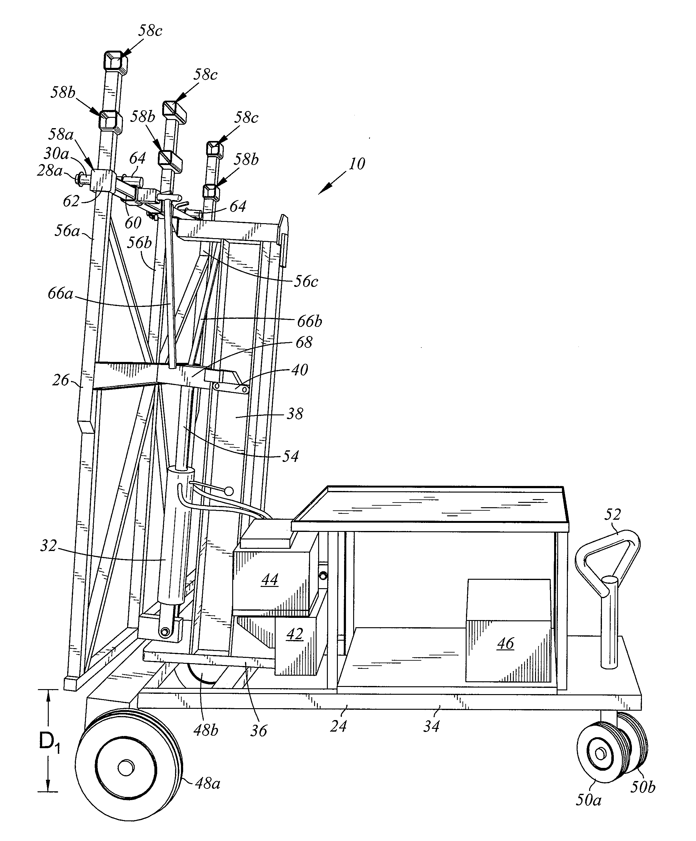
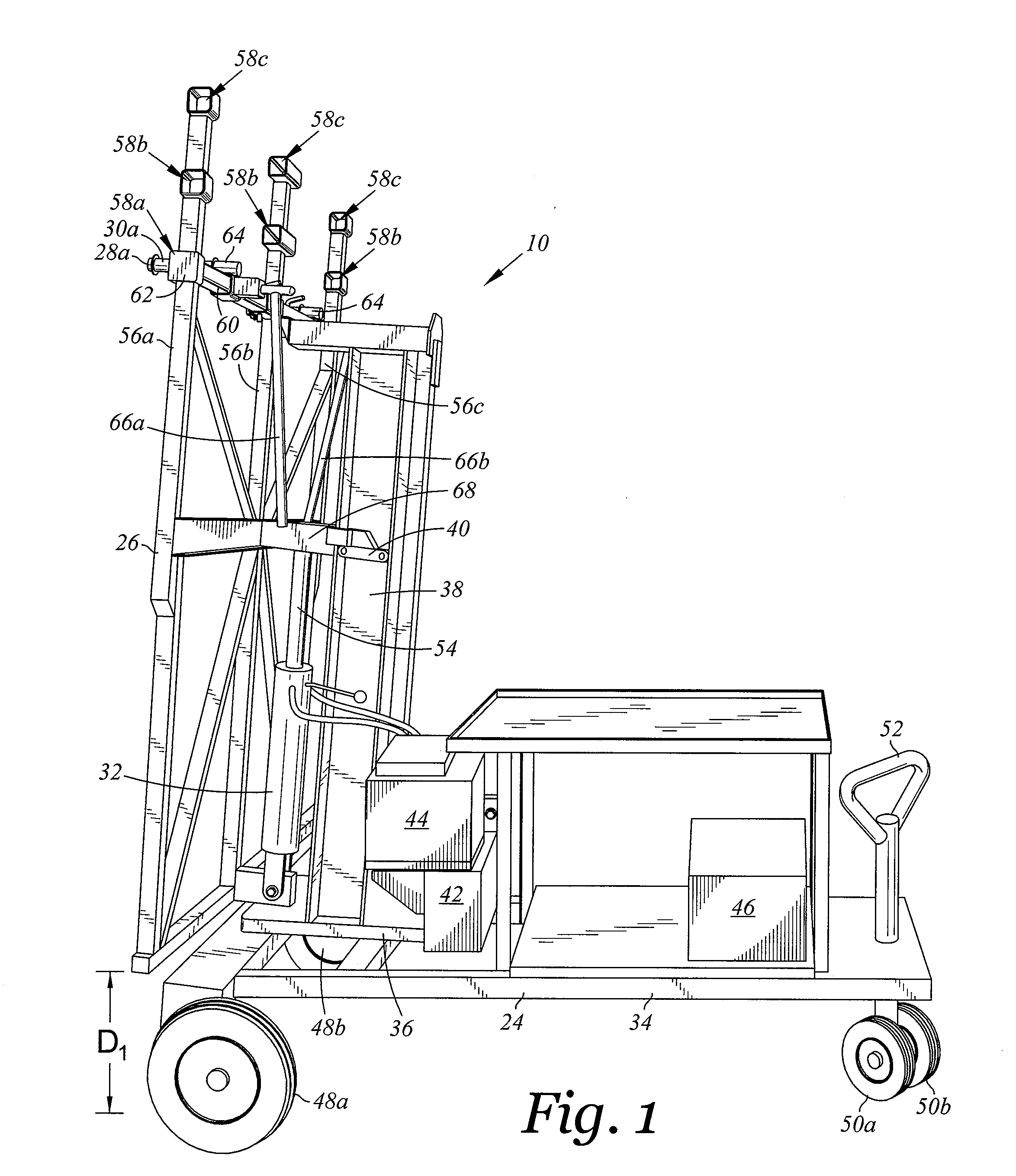
[0033]Referring now to FIG. 1 there is depicted a side perspective view of a wall lifting, transport and positioning device 10. FIG. 2 is a side perspective view of the device 10 of FIG. 1 with a wall section 12. FIG. 3 is a side view of the device 10 of FIG. 1. ...


PUM


Abstract

A wall lifting, transport and positioning device for use with a wall section upon a worksite surface. The wall section has a top plate with a lower top plate side and a bottom plate with a lower bottom plate side. The device includes a wheeled hand cart housing, a support frame, a pair of roller pins, and a lifting actuator. Each of the roller pins including an outer cylindrical element configured to rotate relative to the support frame with the top plate being positioned in contact with the outer cylindrical element for translation of the wall section in a direction along the top plate. The lifting actuator is sized and configured to translate the roller pins upward relative to the wheeled hand cart housing with the outer cylindrical elements being positionable in contact with the lower top plate side. A method of positioning a wall section is also provided.

Description

CROSS-REFERENCE TO RELATED APPLICATIONS[0001]Not ApplicableSTATEMENT RE: FEDERALLY SPONSORED RESEARCH / DEVELOPMENT[0002]Not ApplicableBACKGROUND[0003]1. Technical Field[0004]The present disclosure generally relates to devices and methods for positioning pre-fabricated wall sections, and more particularly, to a wall lifting, transport and positioning device for use with a wall section upon a worksite surface.[0005]2. Related Art[0006]Prefabricated wall panels or wall sections have continued to gain increased popularity due to the relative efficiency in the onsite construction of a structure. These pre-fabricated or pre-engineered wall sections are constructed offsite and delivered to a worksite location ready to be erected. This saves significant onsite construction time and labor to build a similar wall section which then must be erected. The wall sections are delivered to worksite location and may be temporarily stored in horizontal stacked configuration. A wall section may typicall...

Claims


Application Information

Patent Timeline
Patent Type & Authority Applications(United States)
IPC IPC(8): E04G21/16B66F11/00
CPCB66F9/18E04G21/167E04G21/168E04B1/35E04B2001/3588
Inventor HOVENIER, FRED E.HOVENIER, FRED J.
Owner HOVENIER FRED E
Why Eureka
Try Eureka