Combustor flow sleeve with supplemental air supply

a combustor and air supply technology, applied in the combustion process, hot gas positive displacement engine plants, lighting and heating apparatus, etc., can solve the problems of increased pressure loss, different amount of fuel entering each combustor can, and different amount of inlet airflow

Inactive Publication Date: 2013-10-17
GENERAL ELECTRIC CO
View PDF6 Cites 8 Cited by
  • Summary
  • Abstract
  • Description
  • Claims
  • Application Information

AI Technical Summary

Benefits of technology

[0010]In still another aspect, the invention provides a method of controlling flow of air to any one or all of a plurality of combustors in a can-annular array of combustors about a gas turbine rotor, where each combustor includes a liner enclosing a combustion chamber and supports at least one nozzle for supplying fuel to the combustion chamber; and a flow sleeve surrounding the combustor liner, with an annular passage extending between the liner and the flow sleeve for supplying compressor discharge air to the combustion chamber via an axially-oriented inlet at the downstream end of the flow sleeve, the method comprising supplying supplemental air under pressure selectively to the annular passage of each of the plurality of combustors; and modulating flow of the supplemental air to control a fuel / air ratio for any one or all of the plurality of combustors.

Problems solved by technology

Moreover, oftentimes the cooling air is supplied from a compressor coupled in flow communication with the combustion assembly.
There are many benefits to these types of systems, but one of the drawbacks is that each combustion can will experience a different amount of inlet airflow due to factors such as part tolerances, obstructions in the inlet, non-integral stage-one nozzle counts downstream of the combustors, etc.
Also, the amount of fuel entering each combustor can will be slightly different due to variation in fuel nozzle effective areas, obstacles in piping and manifolds, etc.
The air is intended to enter the annulus between the flow sleeve and the combustor liner cleanly; however, it has been found that flow separation occurs at the inlet, along the inside surface of the flow sleeve, causing increased pressure loss.

Method used


Image

  • Combustor flow sleeve with supplemental air supply
  • Combustor flow sleeve with supplemental air supply
  • Combustor flow sleeve with supplemental air supply

Examples


Embodiment Construction

[0019]At the outset, it is noted that, as used herein, “upstream” refers to a forward end of a gas turbine engine or other component in the combination gas flow path, and “downstream” refers to an aft end of a gas turbine engine or other component in the combustion gas flow path.

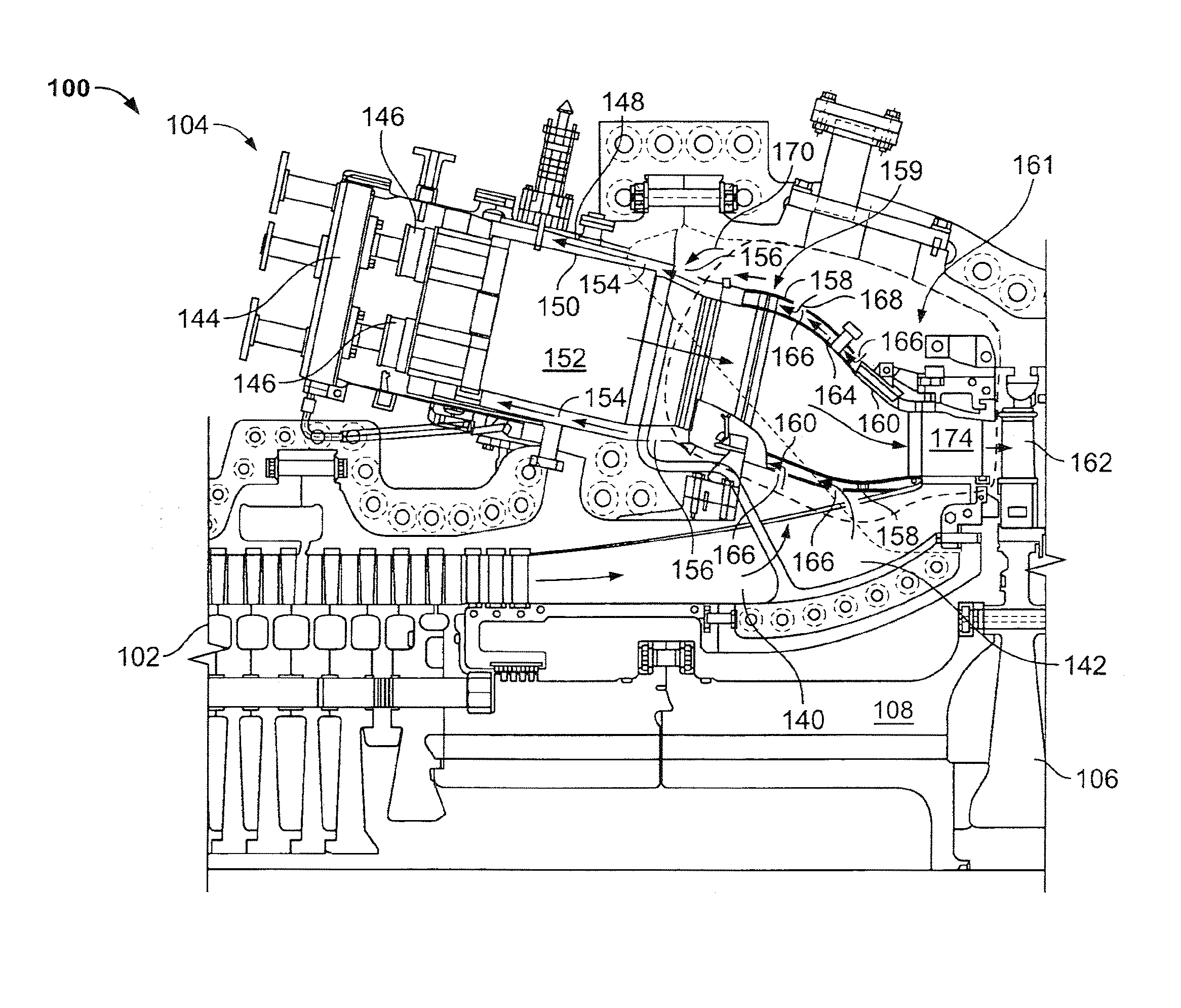
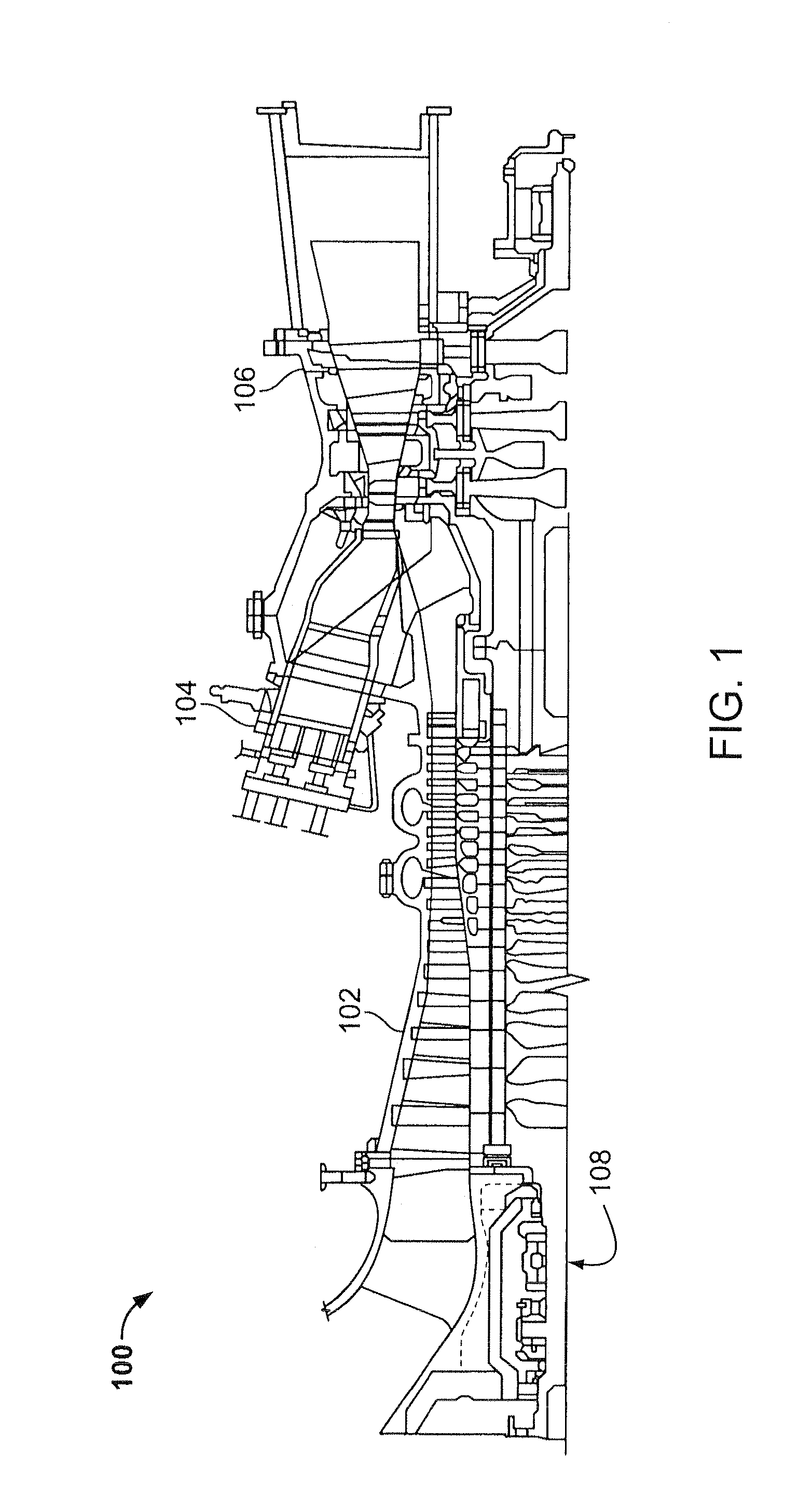
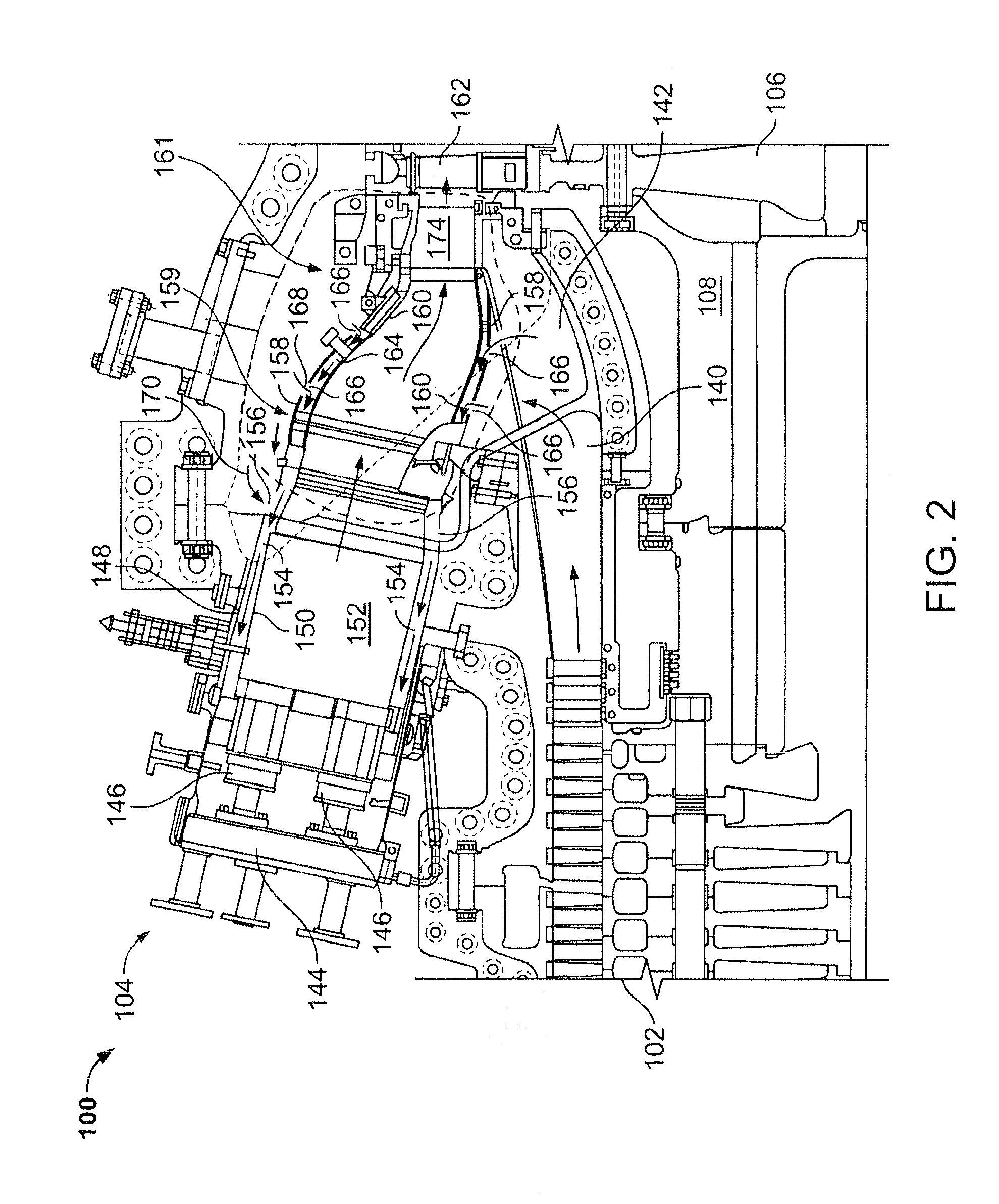
[0020]FIG. 1 is a schematic cross-sectional illustration of an exemplary gas turbine engine 100. Engine 100 includes a compressor assembly 102, a combustor assembly 104, a turbine assembly 106 and a common compressor / turbine rotor shaft 108. It should be noted that engine 100 is exemplary only, and that the present invention may instead be implemented within any gas turbine engine that functions generally as described herein.

[0021]In operation, air flows through compressor assembly 102 and compressed air is discharged to combustor assembly 104. Combustor assembly 104 injects fuel, for example, natural gas and / or fuel oil, into the air flow; ignites the fuel-air mixture to expand the fuel-air mixture through ...


PUM


Abstract

A gas turbine combustor includes a combustor liner enclosing a combustion chamber; at least one fuel nozzle arranged to provide fuel to the combustion chamber; a flow sleeve surrounding the combustor liner forming a passage radially between the combustor liner and the flow sleeve for supplying air to the combustion chamber, the flow sleeve configured to permit air to flow substantially axially into the passage via a substantially annular flow sleeve inlet. A downstream end of the flow sleeve is formed to include an annular manifold provided with plural outlets about a circumference of the downstream end of the flow sleeve and adapted to supply supplemental air from an external variable air source substantially radially into the passage to thereby maintain axial air flow boundary layer attachment at the flow sleeve inlet.

Description

BACKGROUND OF THE INVENTION[0001]This invention relates generally to gas turbine engines and more particularly, to gas turbine combustor assemblies.[0002]At least some known gas turbine engines use cooling air to cool a combustion assembly within the engine. Moreover, oftentimes the cooling air is supplied from a compressor coupled in flow communication with the combustion assembly. For example, in at least some known gas turbine engines, the cooling air is discharged from the compressor into a plenum extending at least partially around a transition piece of the combustor assembly. A first portion of the cooling air entering the plenum is supplied to an impingement sleeve surrounding the transition piece prior to entering a cooling channel radially between the impingement sleeve and the transition piece. Cooling air entering the cooling channel is discharged into a second, aligned cooling channel radially between a combustor liner and a flow sleeve. The remaining cooling air enterin...

Claims


Application Information

Patent Timeline
Patent Type & Authority Applications(United States)
IPC IPC(8): F02C3/14F23R3/28F23R3/16
CPCF23R3/04F23R3/26
Inventor HUGHES, MICHAEL JOHN
Owner GENERAL ELECTRIC CO
Why Eureka
Try Eureka