Supercharge Your Innovation With Domain-Expert AI Agents!

Apparatus And Method For Electromagnetic Stirring In An Electrical Arc Furnace

Active Publication Date: 2013-10-17
ABB (SCHWEIZ) AG
View PDF2 Cites 8 Cited by
  • Summary
  • Abstract
  • Description
  • Claims
  • Application Information

AI Technical Summary

Benefits of technology

The invention provides an apparatus and method for stirring the contents of an electrical arc furnace using electromagnetic stirrer units. These units have separate coils wrapped around a core and can be positioned flexibly for effective stirring. A shield made of non-magnetic material is placed between the core and the winding to reduce the magnetic field on the furnace's surfaces. Additionally, the cores may have bends to better match the shape of the furnace and minimize energy use while still achieving strong stirring forces. The invention is simple, reliable, and low-cost.

Problems solved by technology

Thus, in installations of EMS at DC EAF's, it is not possible to place the stirrer unit at a central position below the bottom of the furnace.
Further, prior art stirrer units for DC and AC EAF's seem to be inflexible and do not provide adequate stirring for all kind of applications.

Method used


Image

  • Apparatus And Method For Electromagnetic Stirring In An Electrical Arc Furnace
  • Apparatus And Method For Electromagnetic Stirring In An Electrical Arc Furnace
  • Apparatus And Method For Electromagnetic Stirring In An Electrical Arc Furnace

Examples


Embodiment Construction

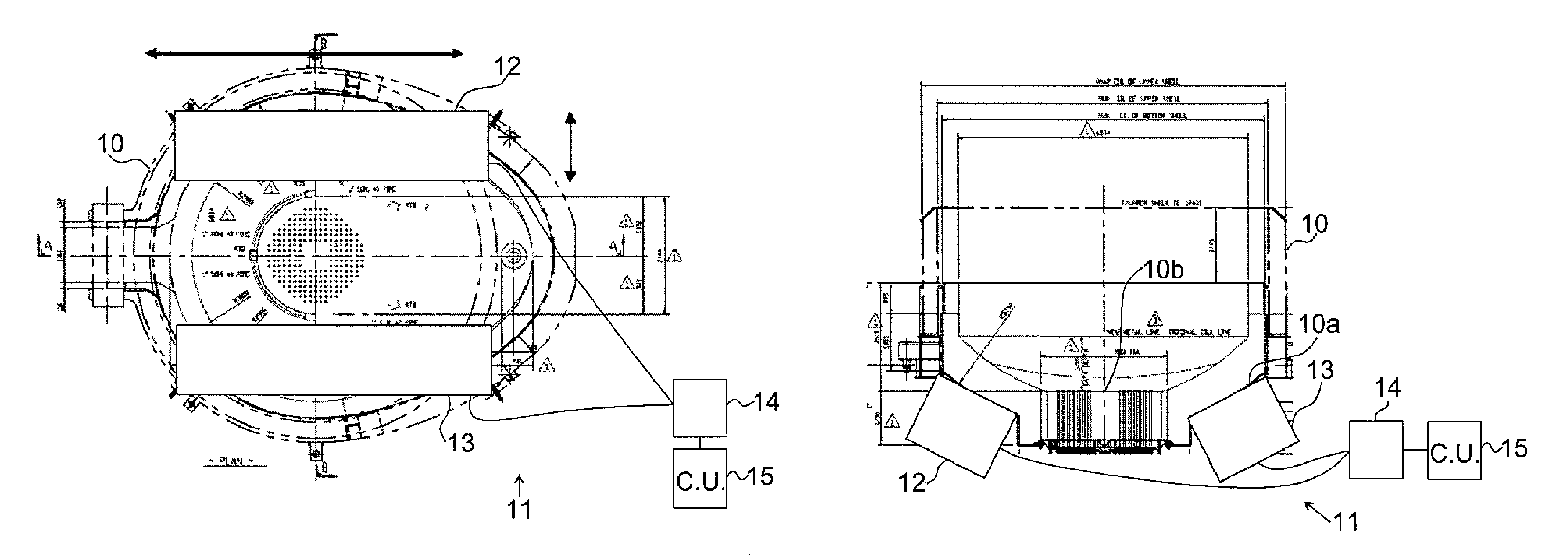
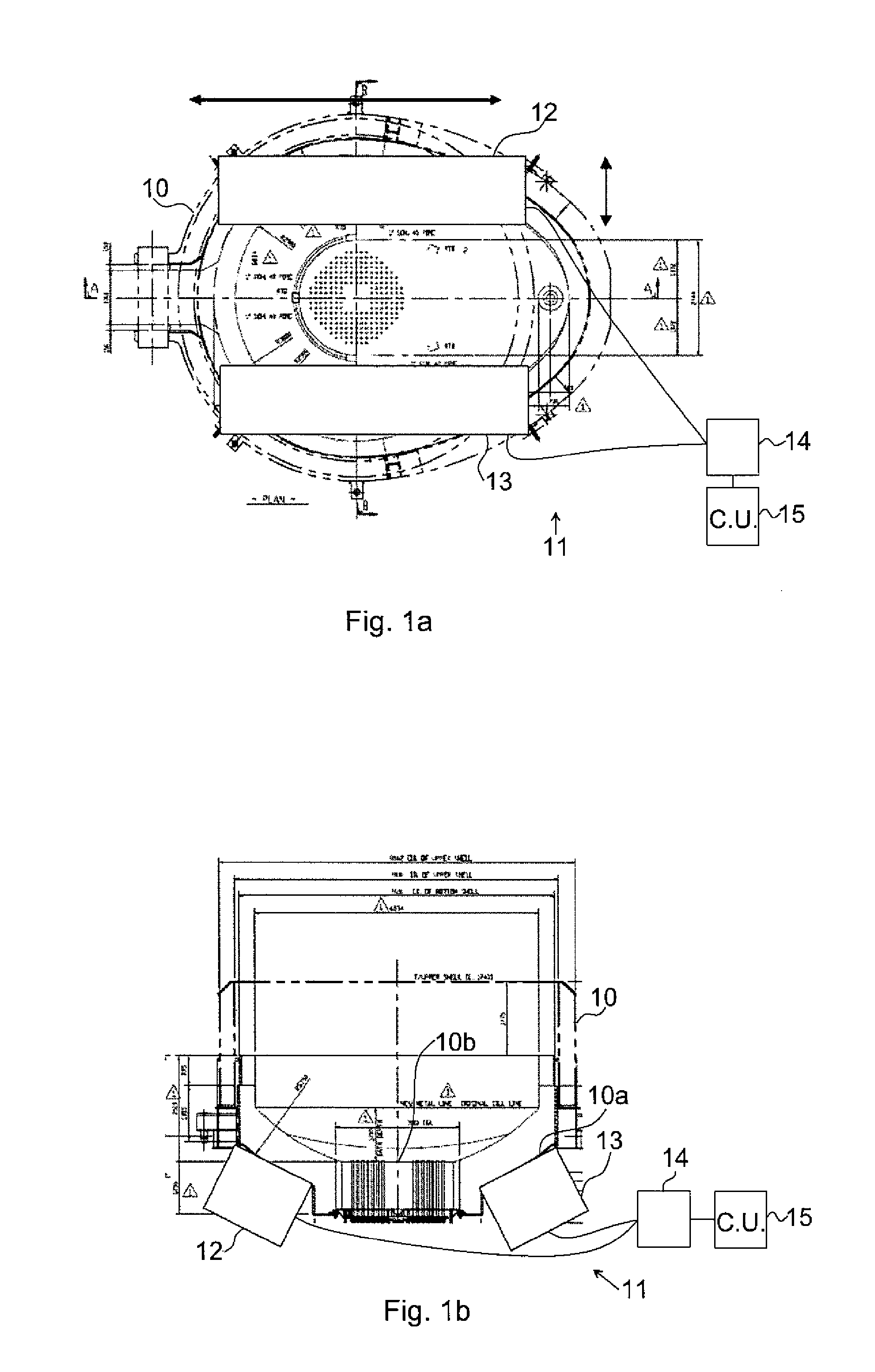
[0022]In FIGS. 1a-b is illustrated an electrical arc furnace (EAF) 10, in which an apparatus 11 for electromagnetic stirring of the steel melt in the EAF 10 according to one embodiment of the invention is implemented. The EAF may be a DC EAF as illustrated or an AC EAF.

[0023]The apparatus 11 for electromagnetic stirring comprises two electromagnetic stirrer units 12, 13, a single current supply system 14 operatively connected to the two electromagnetic stirrer units 12, 13, and a control unit 15 operatively connected to the single current supply system 14 to control the operation of the two electromagnetic stirrer units 12, 13. The two electromagnetic stirrer units 12, 13 are mounted on an outer bottom surface 10a of the EAF at opposite sides of a central position 10b of the bottom surface 10a. The DC EAF has typically a DC bottom electrode 10c located at the central position 10b of the bottom surface 10a and the two electromagnetic stirrer units are thus mounted on opposite sides o...


PUM

PropertyMeasurementUnit
Currentaaaaaaaaaa
Shapeaaaaaaaaaa
Electromagnetic fieldaaaaaaaaaa

Abstract

An apparatus for electromagnetic stirring of the steel melt in an electrical arc furnace includes two electromagnetic stirrer units, a current supply, and a control unit. The two stirrers are mounted on an outer bottom surface of the electrical arc furnace at opposites sides of a central position of the bottom surface, the current supply is operatively connected to the two electromagnetic stirrer units, and the control unit is operatively connected to the current supply to control the operation of the two electromagnetic stirrer units.

Description

FIELD OF THE INVENTION[0001]The present invention generally relates to electromagnetic stirring of the steel melt in AC or DC electrical arc furnaces.BACKGROUND OF THE INVENTION[0002]Electromagnetic stirring (EMS) of the steel melt in electrical arc furnaces (EAF) are beneficial of several reasons, for example to improve melt speed and reduce process time, to improve temperature homogenization, to reduce energy consumption, and to prevent vortex formation during taping.[0003]In earlier installations of EMS's at AC EAF's, the stirrer unit is mounted below the bottom at a central position. In DC EAF's the DC current is collected in a large electrode that is integrated into the bottom refractory of the furnace. The electrode is connected to the outside through the bottom. The bottom electrode area is very large (typically 2×3 m).[0004]Thus, in installations of EMS at DC EAF's, it is not possible to place the stirrer unit at a central position below the bottom of the furnace. Normally, ...

Claims


Application Information

Patent Timeline
IPC IPC(8): B01F13/08C21C7/00
CPCB01F13/0809C21C7/00C21C5/52F27B3/10F27D27/00Y02P10/20B01F33/451
Inventor ERIKSSON, JAN-ERIKRAHMANI, MOHAMED ALIWIDLUND, OLAHJORTSTAM, OLOFBEL FDHILA, REBEISANDER-TAVALLAEY, SHIVASAND, ULFZHANG, XIAOJINGKROON, TORD
Owner ABB (SCHWEIZ) AG
Features
  • R&D
  • Intellectual Property
  • Life Sciences
  • Materials
  • Tech Scout
  • Unparalleled Data Quality
  • Higher Quality Content
  • 60% Fewer Hallucinations
Learn More