Filtration device and method

a technology of filtration device and filter body, which is applied in the direction of filtration separation, separation process, laboratory glassware, etc., can solve the problems of ineffective sealing contact, complicated assembly of filtration device, and complicated plunger body manufacture, so as to improve the sealing effect

Active Publication Date: 2013-10-17
GLOBAL LIFE SCI SOLUTIONS GERMANY GMBH
View PDF7 Cites 17 Cited by
  • Summary
  • Abstract
  • Description
  • Claims
  • Application Information

AI Technical Summary

Benefits of technology

[0041]Alternatively or additionally, the flexible portion comprises a skirt extending downward from the first end of the plunger body, the skirt being deflectable inwards. The skirt may form a wall of a recess portion, the recess portion being arranged to receive liquid during said movement so that the received liquid exerts an outward force on said skirt. Further, where a recess is used, liquid received in the recess exerts a further outward pressure on the skirt, further improving the effectiveness of the seal.
[0042]Preferably, the said plunger body is tapered so as to narrow towards said first aperture. This prevents misalignment of the plunger body in the liquid receptacle, ensuring that the seals engage effectively.

Problems solved by technology

This makes assembly of the filtration device complicated, particularly in view of the fact that such seals are typically small and difficult to handle during automated or manual assembly; further, locating grooves or other structures may be required in the plunger body, complicating the manufacture of the plunger body.
Further, in order for the sealing contact mentioned above to be effective, a relatively tight fit between the O-ring and the interior walls of the tubular vial is required; if the fit is too loose, the sealing contact becomes ineffective, allowing the liquid sample to escape around the sides of the plunger, rather than though the filter membrane.
On the other hand, if the fit is too tight, the force required to push the plunger into the tubular vial may become excessive, making the device difficult to operate; furthermore, the tubular vial may break under excessive force.
However, plastics materials are often susceptible to leaching by the liquid sample, which may result in the liquid sample being contaminated with impurities from the plastics material prior to filtration, which impurities may not all be removed during the filtration process.
However, glass vials typically have a greater variation in internal diameter from vial to vial than plastics vials, making them unsuitable for use with the plungers described above.
In addition, conventional glass vials are generally not as strong as plastics vials, particularly when subjected to expansive forces exerted by compressed plunger seals or fluids being compressed as the plunger is forced into the vial.

Method used


Image

  • Filtration device and method
  • Filtration device and method
  • Filtration device and method

Examples


Embodiment Construction

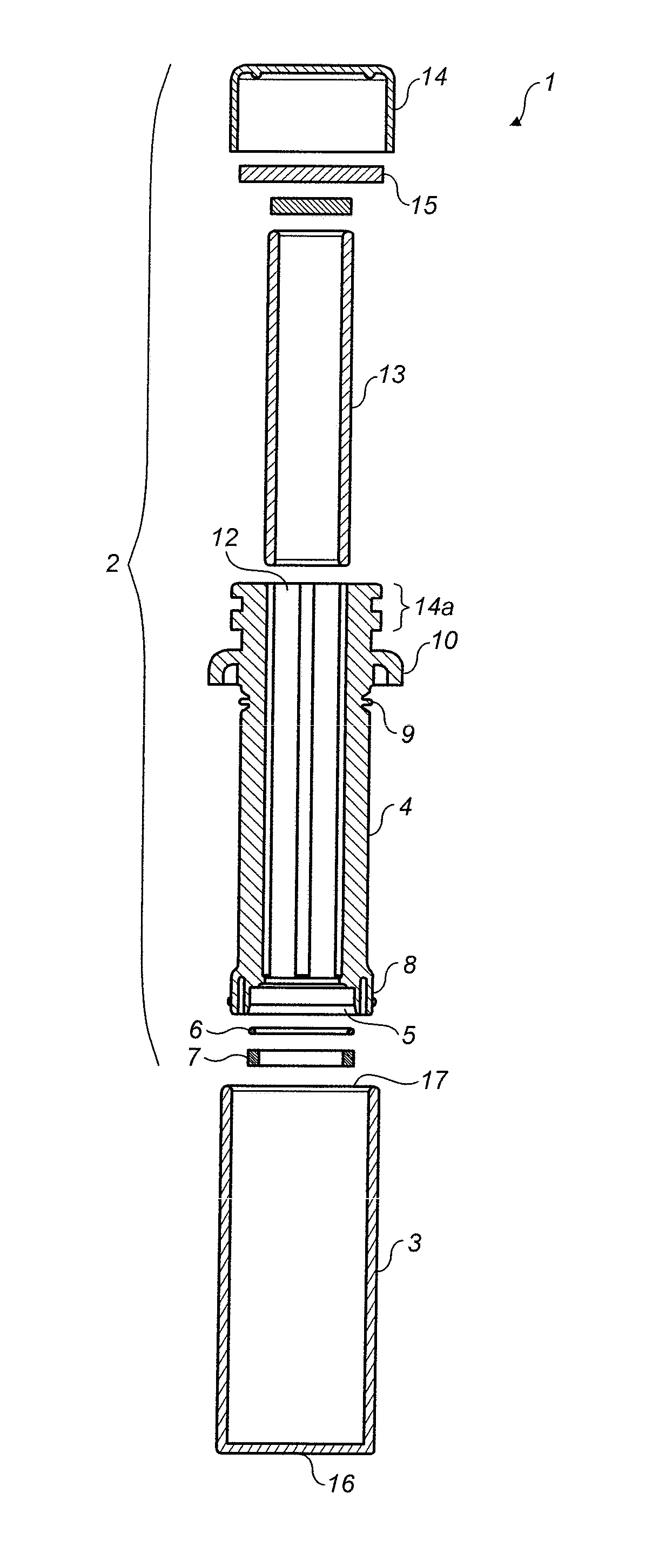
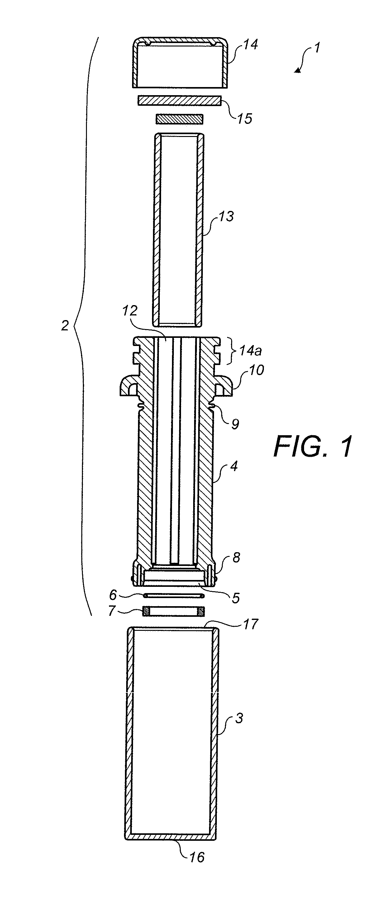
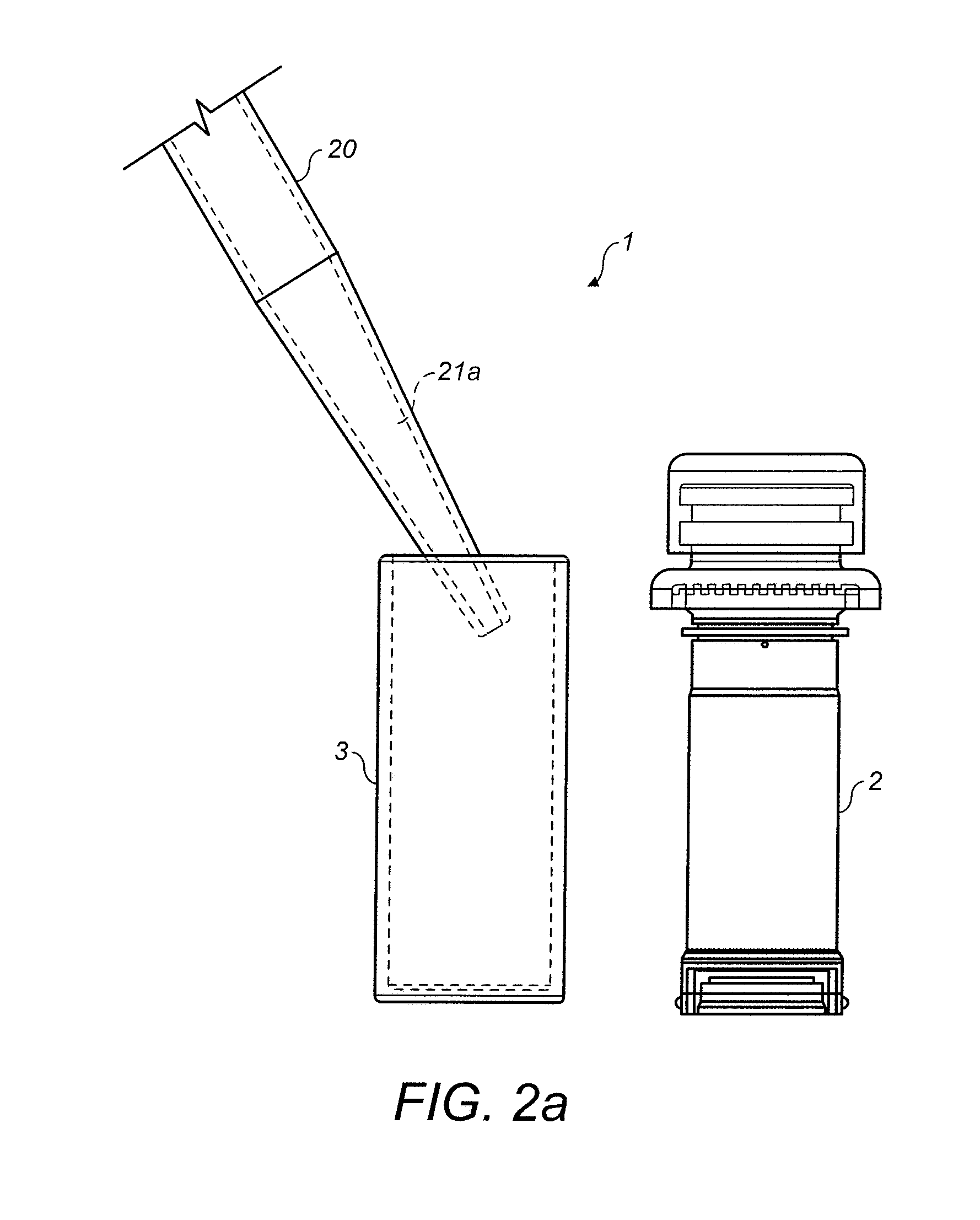
[0073]FIG. 1 shows an exploded cross-sectional view of a filtration apparatus 1 according to an embodiment of the invention. The filtration apparatus 1 includes a filtration device in the form of a plunger assembly 2 and a sample receptacle, in the form of a vial 3, into which a liquid sample is placed prior to filtration.

[0074]The plunger assembly 2 comprises a plunger body 4, which has an aperture 5 at one end, in which is located a filter membrane 6, which may be held in the aperture 5 by a retaining ring 7; the retaining ring may affix the filter membrane by interference fitting or snap-fitting, for example. Alternatively, ultrasonic welding could be used to fix the retaining ring 7 to the aperture 5, thereby holding the filter membrane 6 in place.

[0075]The filter membrane 6 is typically a porous membrane having a pore size selected to allow the liquid sample 21 to pass through, but to filter out unwanted particles; a typical pore size is 0.2 μm to 0.45 μm. The filter membrane 6...


PUM

PropertyMeasurementUnit
diameteraaaaaaaaaa
diameteraaaaaaaaaa
lengthaaaaaaaaaa

Abstract

Embodiments of the present invention relate to a filtration device for use in filtration of a liquid, and disclose: a liquid receptacle having an open end and a closed end; a plunger body moveable at least partially within the liquid receptacle along an axis said axis extending between the open and closed ends, said plunger including a filtrate chamber in fluid communication with the liquid receptacle via a fluid filtering path and a filter disposed in the filtering path, and the device further including a slidable seal for inhibiting or preventing fluid flow across the seal during said plunger movement; wherein said seal includes a first skirt depending from the plunger at one end of the first skirt, said first skirt having an outer surface which in use slidably and sealingly abuts the vial, and having, at least in an uncompressed state, a generally annular separation between the skirt and the plunger body, which separation extends generally parallel to the axis. A second skirt, overlapping the first skirt, is disclosed also.

Description

FIELD OF THE INVENTION[0001]The present invention relates to filtration devices and methods for filtering liquid samples and in particular to filtration devices in which a plunger including a filter material is inserted into a liquid receptacle such as a vial.BACKGROUND OF THE INVENTION[0002]Filtration devices comprising a hollow plunger which slides within a hollow tubular vial are frequently employed in laboratory and other environments to remove solids from a liquid sample. For example, biological samples such a blood, mucus or urine may be filtered (to remove contaminants or unwanted protein for example), the filtrate being subsequently used to perform medical or other tests.[0003]In such devices, the hollow plunger typically has an aperture at one end, which is fitted with a filter membrane. The liquid sample to be filtered is initially held in the tubular vial, which is open at one end and closed at the other. The hollow plunger is inserted into the tubular vial, with a sealin...

Claims


Application Information

Patent Timeline
Patent Type & Authority Applications(United States)
IPC IPC(8): B01D29/11B01L3/00
CPCB01D29/118B01L3/00B01L3/502B01L3/508B01L2200/0684B01L2200/141B01L2300/0681B01L2300/0832B01L2400/0478B01D33/01
Inventor TORTORELLA, STEVAN PAULSEYMOUR, GERAINT
Owner GLOBAL LIFE SCI SOLUTIONS GERMANY GMBH
Why Eureka
Try Eureka