Illumination system

a technology of illumination system and light source, which is applied in the direction of electric lighting source, electric light source, lighting apparatus, etc., can solve the problems of glaring bright light, user discomfort, delay a bit of time,

Inactive Publication Date: 2013-10-17
LEXTAR ELECTRONICS CORP
View PDF9 Cites 5 Cited by
  • Summary
  • Abstract
  • Description
  • Claims
  • Application Information

AI Technical Summary

Benefits of technology

[0008]It is an object of the present invention to provide a brightness adjustable illumination system that has better brightness adjusting effects.
[0010]In a preferred embodiment, the light modulation signal is a pulse-width modulation signal. The driver module generates according to the pulse-width modulation signal the driving voltage having the corresponding amplitude. When the environment brightness signal is lower than a default lowest brightness threshold, the control module slows down a duty cycle of the pulse-width modulation signal so that the activation time slows down. When the environment brightness signal is higher than a default highest brightness threshold, the control module speeds up the duty cycle of the pulse-width modulation signal so that the activation time speeds up.
[0011]In another preferred embodiment, the light modulation signal is a direct current voltage level signal to provide the driver module to generate according to the direct current voltage level signal the driving voltage having corresponding amplitude. When the environment brightness signal is lower than a default lowest brightness threshold, the control module slows down the speed of voltage increase of the direct current voltage level signal such that the speed at which the driving voltage increases to the operating voltage slows down. When the environment brightness signal is higher than a default highest brightness threshold, the control module speeds up the speed of voltage increase of the direct current voltage level signal such that the speed at which the driving voltage increases to the operating voltage speeds up.

Problems solved by technology

Under these circumstances, since the users' eyes are accustomed to the dark environment already, the sudden bright light will be glaring for users.
As a result, users will experience unnecessary discomfort.
In addition, there are a few illumination systems having soft start designs that can delay a bit of time to avoid instantaneously outputting 100% light.
Although this type of design may overcome the deficiency of the mentioned lamp 4, it would still have the problem of activating too slow if the lamp were to be turned on under bright environment light circumstances.

Method used


Image

  • Illumination system
  • Illumination system
  • Illumination system

Examples


Embodiment Construction

[0017]An illumination system is provided that can control the activation time thereof by sensing the environment brightness.

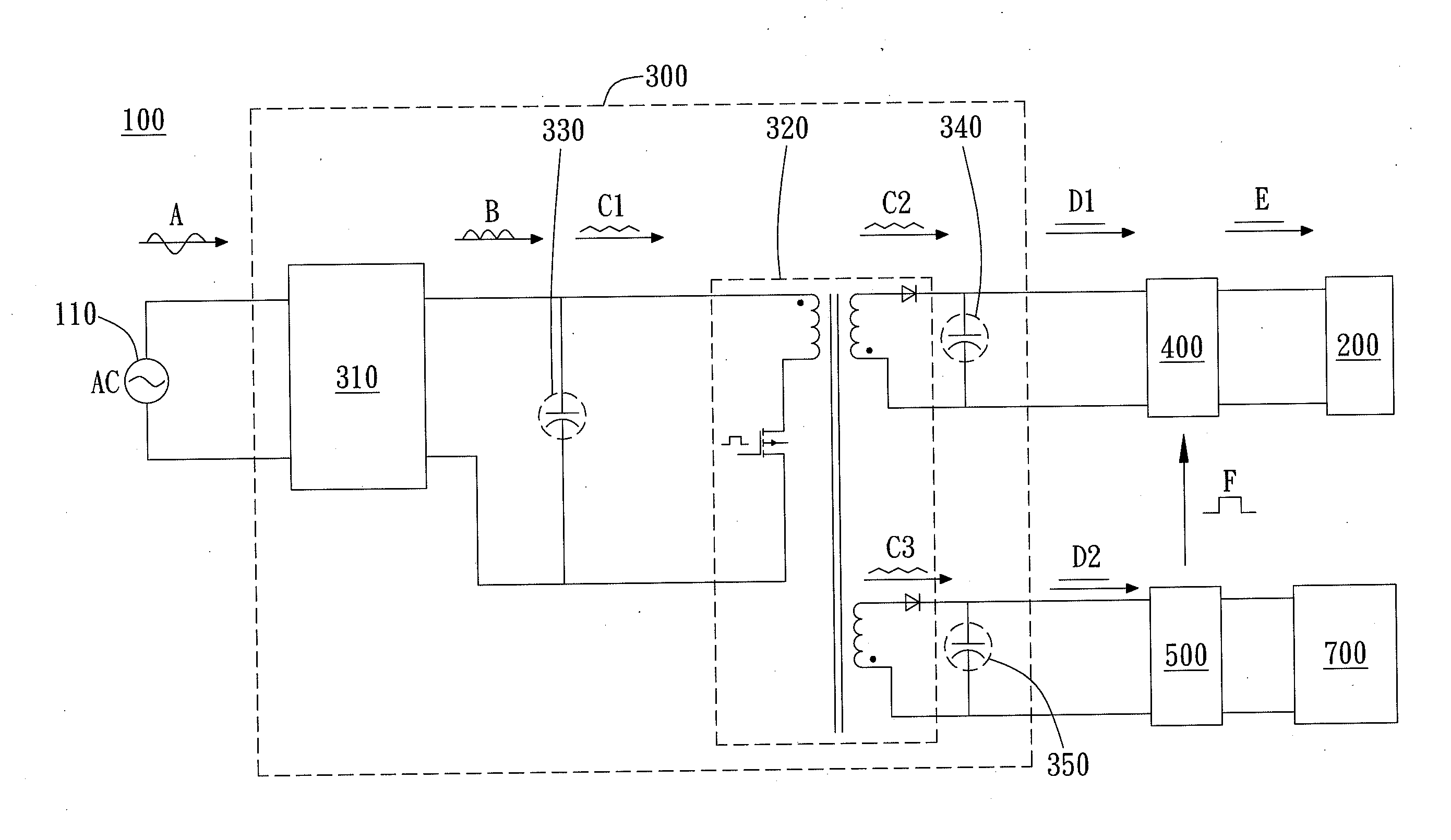
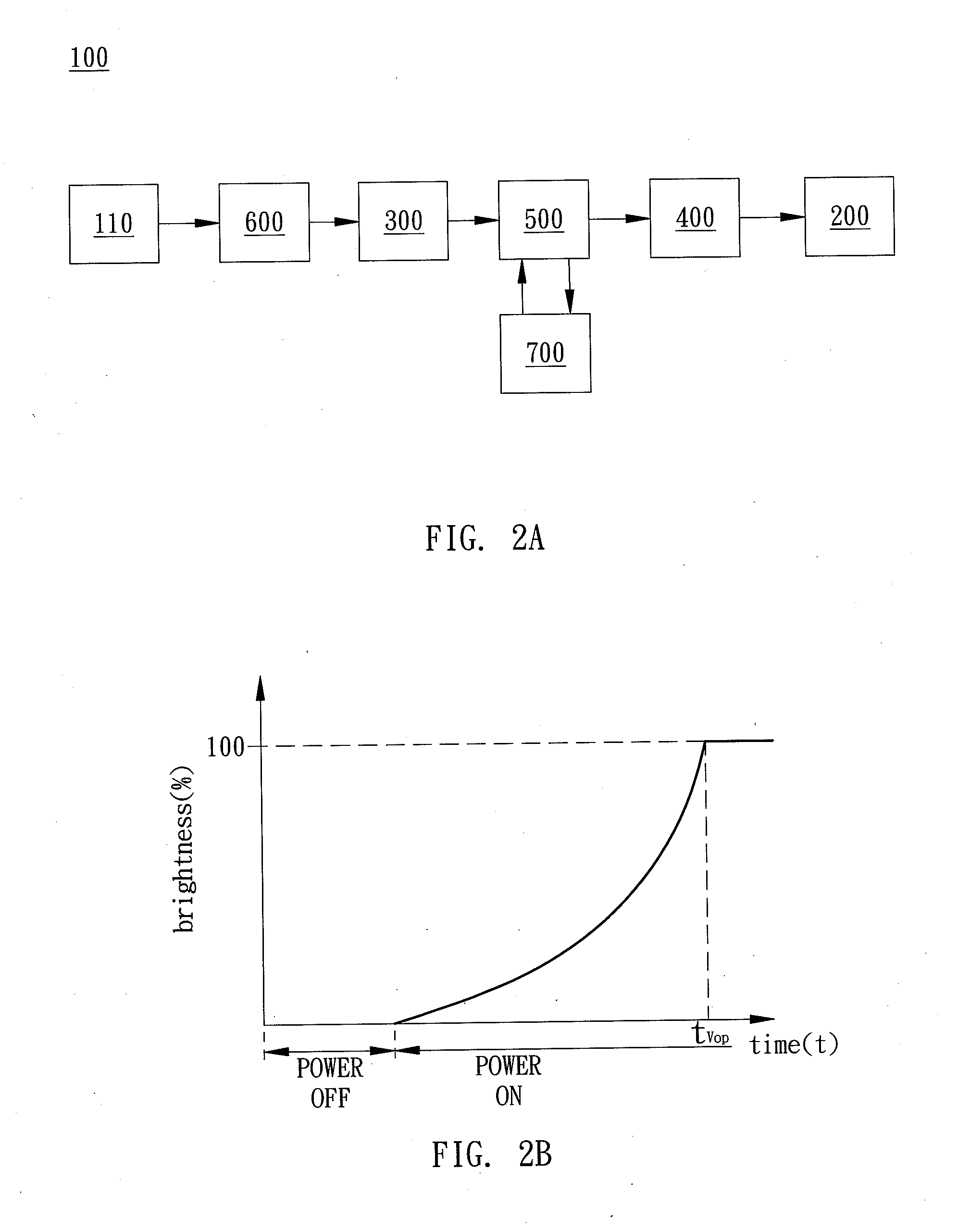
[0018]Referring to FIG. 2A of a preferred embodiment of the illumination system 100 of the present invention. The illumination system 100 includes a light source module 200, a power module 300, a driver module 400, a control module 500, and a light sensor module 700. As shown in FIG. 2A, the power module 300 is coupled to the control module 500. The control module 500 is respectively connected to the light sensor module 700 and the driver module 400. The light source module 200 in turn is connected to the driver module 400. In the present embodiment, the light source module 200 is preferably a light-emitting diode (LED) module. It should be noted that the light source module 200 of the illumination system 100 is not limited to being a single LED lamp. The light source module 200 may also be implemented as an incandescent light bulb, fluorescent light tube, and / ...


PUM


Abstract

An illumination system includes a light module, a power module, a driver module, a light sensor module, and a control module. The power module is coupled to an input power source. The power module converts the input power source and outputs a direct voltage. The driver module, coupled between the light module and the power module, converts the direct voltage into a driving voltage and then outputs a driving current to drive the light module. The light sensor module senses an environment brightness and outputs a brightness signal. The control module receives the brightness signal and outputs a light modulation signal to the driver module, wherein the driver module controls the activation time of the light module according to the light modulation signal.

Description

BACKGROUND OF THE INVENTION[0001]1. Field of the Invention[0002]The present invention generally relates to an illumination system. Particularly, the present invention relates to an illumination system with adjustable brightness levels.[0003]2. Description of the Prior Art[0004]Current illumination systems, such as table lamps, are widely used lamp products. As demand and requirements by lamp users increase along with increasing competition between manufacturers on the market, lamp manufacturers have gradually started to push out even more user friendly lamp products in order to satiate users' needs and requirements. As such, whether an illumination system is user friendly or not has become a key factor in the determination of the competitiveness of a product with other related products.[0005]FIG. 1A illustrates a diagram of an electrical circuit of a conventional illumination system. As shown in FIG. 1A, the conventional illumination system includes a power source 1, a lamp switch 2...

Claims


Application Information

Patent Timeline
Patent Type & Authority Applications(United States)
IPC IPC(8): H05B37/02H05B44/00
CPCH05B37/02H05B47/16Y02B20/40H05B45/12H05B47/11H05B45/385H05B45/382H05B47/10H05B31/50
Inventor WU, EN-MIN
Owner LEXTAR ELECTRONICS CORP
Why Eureka
Try Eureka