

Filter device, manufacturing method for filter device, and duplexer
a filter device and manufacturing method technology, applied in the direction of synthetic resin layered products, coatings, chemistry apparatus and processes, etc., can solve the problems of difficult miniaturization of elements and increase in substrate size, and achieve excellent isolation characteristics
- Summary
- Abstract
- Description
- Claims
- Application Information
AI Technical Summary
Benefits of technology
Problems solved by technology
Method used
Image

Examples
embodiment 1
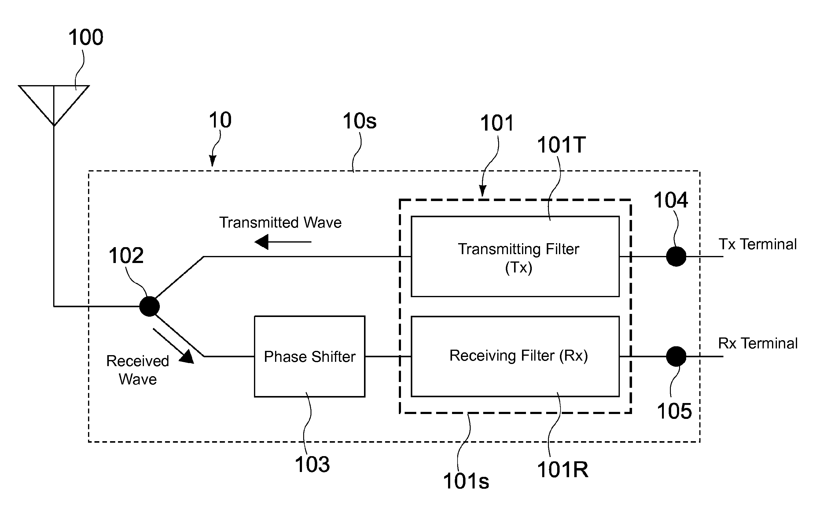
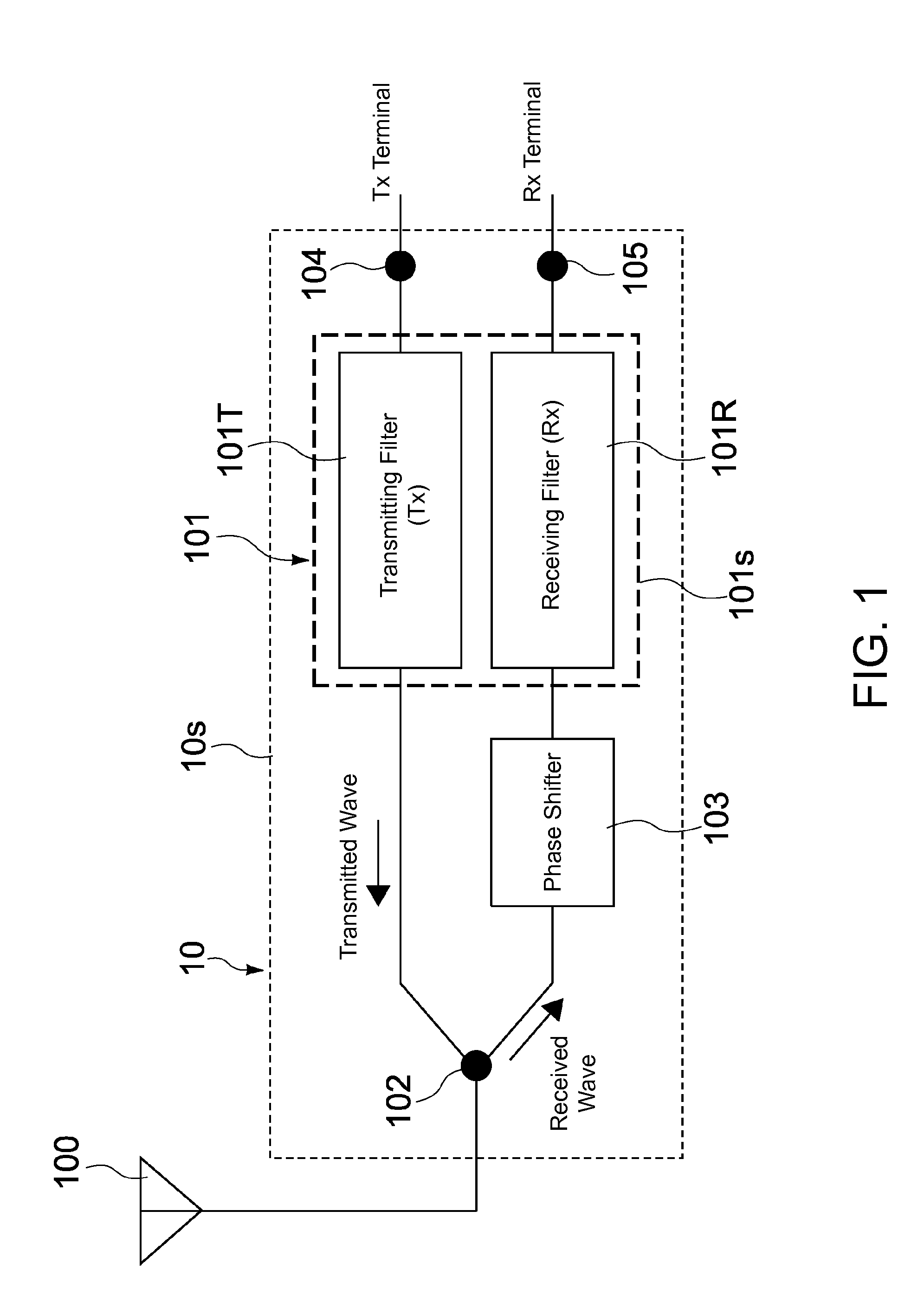
[0088]FIG. 1 is a block diagram that shows a configuration of a duplexer according to one embodiment of the present invention. First, a configuration of the duplexer will be described.
[0089]A duplexer 10 of the present embodiment is a device that splits transmitted and received signals and is installed on a mobile communication device such as a mobile telephone. The duplexer 10 is used in a communication system such as FDD (frequency division duplex), which includes UMTS (universal mobile telecommunications system) and CDMA (code division multiple access), for example.
[0090]The duplexer 10 has the role of splitting the transmitted and received signals in order to use a single antenna for both transmitting and receiving signals. In order to realize this, the following properties are necessary.
[0091](1) There is little leakage of the transmitted signal to the receiving signal band, and little leakage of the received signal to the transmitting signal band.
[0092](2) An impedance Zt of t...
embodiment 2
[0170]FIG. 7 is a schematic cross-sectional view that shows a configuration of a transmitting / receiving filter according to Embodiment 2 of the present invention. Configurations that differ from those of Embodiment 1 will mainly be described below. Configurations similar to the above embodiment are assigned similar reference characters, and descriptions thereof are omitted or simplified.
[0171]A transmitting / receiving filter 201 of the present embodiment includes a transmitting filter 201T, a receiving filter 201R, and a support substrate 201s. The transmitting filter 201T has an FBAR as a first resonator ER21, and is formed in a first region R1 on the support substrate 201s. The receiving filter 201R has a Lamb wave device as a second resonator ER22, and is formed in a second region R2 on the support substrate 201s.
[0172]The first resonator ER21 has a lower electrode layer 231 (first electrode layer), an upper electrode layer 232 (second electrode layer), and a piezoelectric layer ...
embodiment 3
[0191]FIG. 9 is a schematic cross-sectional view that shows a configuration of a transmitting / receiving filter according to Embodiment 3 of the present invention. Configurations that differ from those of Embodiment 1 will mainly be described below. Configurations similar to the above embodiment are assigned similar reference characters, and descriptions thereof are omitted or simplified.
[0192]A transmitting / receiving filter 301 of the present embodiment has a transmitting filter 301T, a receiving filter 301R, and a support substrate 301s. The transmitting filter 301T has an SMR as a first resonator ER31, and is formed in a first region R1 on the support substrate 301s. The receiving filter 301R has a Lamb wave device as a second resonator ER32, and is formed in a second region R2 on the support substrate 301s.
[0193]The first resonator ER31 has a lower electrode layer 331 (first electrode layer), an upper electrode layer 332 (second electrode layer), and a piezoelectric layer 333 (f...
PUM
| Property | Measurement | Unit |
|---|---|---|
| Thickness | aaaaa | aaaaa |
| Elastic wave | aaaaa | aaaaa |
| Elasticity | aaaaa | aaaaa |
Abstract
Description
Claims
Application Information