Multi-speed OCT swept source with optimized k-clock

a swept source and multi-speed technology, applied in the direction of measuring devices, instruments, using optical means, etc., can solve the problems of resampling being problematic, and traditionally having difficulty in adapting to different sweep rates in an optimal fashion

Active Publication Date: 2013-10-17
EXCELITAS TECH
View PDF7 Cites 26 Cited by
  • Summary
  • Abstract
  • Description
  • Claims
  • Application Information

AI Technical Summary

Benefits of technology

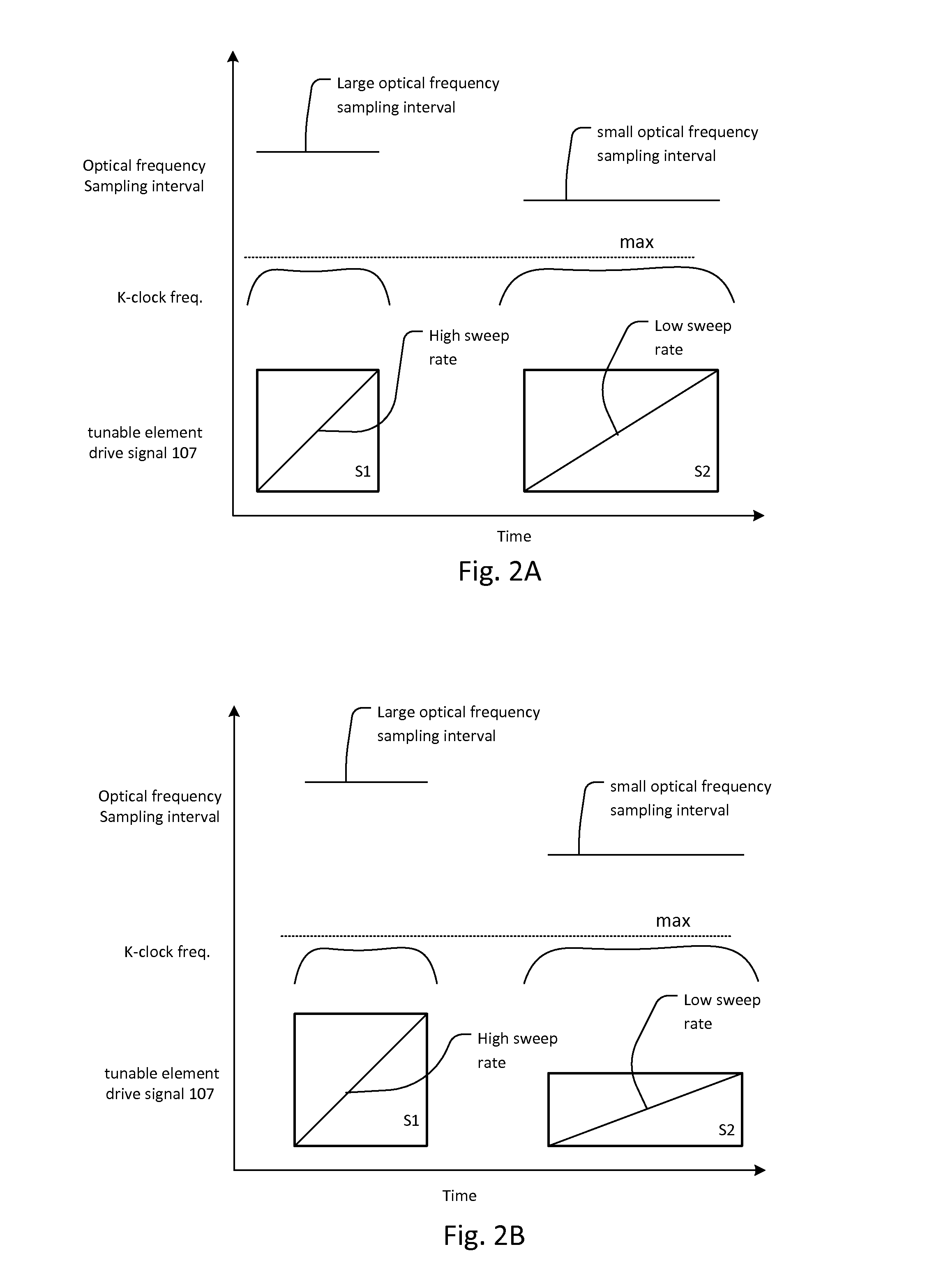
[0027]In some applications, the higher scan or sweep rate mode will have a larger wavelength sweep (scan band) than for the lower scan or sweep rate. Alternatively, a scan band for a higher one of the scan or sweep rates is substantially the same as the scan band for the lower one of the scan sweep rates, for the optical swept source system. This allows tradeoffs between speed, maximum depth, and spatial resolution.

Problems solved by technology

In a system that does not use a k-clock, but instead uses resampling, the challenge is simply to find a swept source that can scan at more than one sweep rate.
As noted previously, however, resampling is problematic because it requires oversampling of the interference signal.
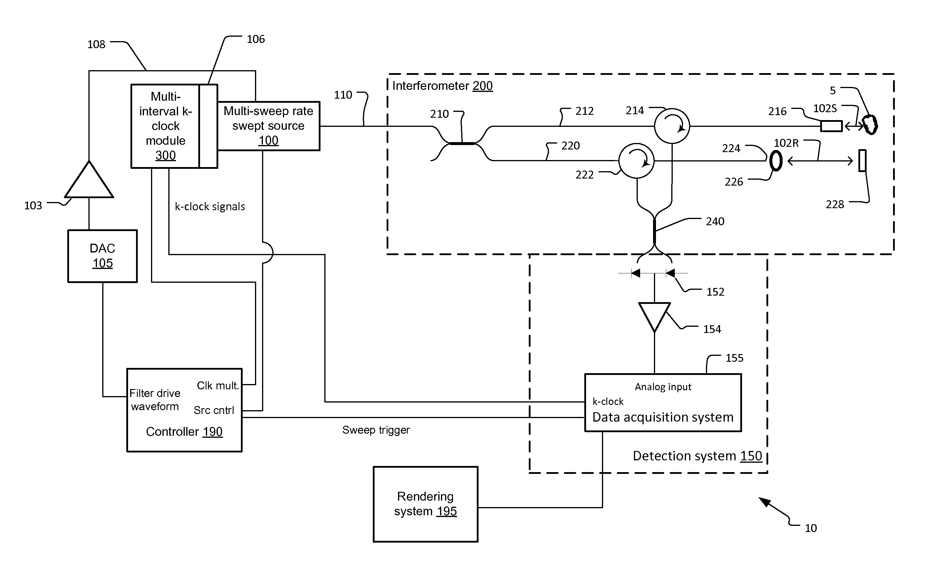
The problem with OCT systems that have multi-sweep rate swept sources and k-clock systems is that they have traditionally had difficulty adapting to different sweep rates in an optimal fashion.

Method used


Image

  • Multi-speed OCT swept source with optimized k-clock
  • Multi-speed OCT swept source with optimized k-clock
  • Multi-speed OCT swept source with optimized k-clock

Examples


Embodiment Construction

[0052]The invention now will be described more fully hereinafter with reference to the accompanying drawings, in which illustrative embodiments of the invention are shown. This invention may, however, be embodied in many different forms and should not be construed as limited to the embodiments set forth herein; rather, these embodiments are provided so that this disclosure will be thorough and complete, and will fully convey the scope of the invention to those skilled in the art.

[0053]As used herein, the term “and / or” includes any and all combinations of one or more of the associated listed items. Further, the singular forms of the articles “a”, “an” and “the” are intended to include the plural forms as well, unless expressly stated otherwise. It will be further understood that the terms such as includes, comprises, including and / or comprising, when used in this specification, specify the presence of stated features, integers, steps, operations, elements, and / or components, but do n...


PUM


Abstract

An optical coherence tomography system utilizes an optical swept source that frequency scans at least two different sweep rates. In this way, the system can perform large depth scans of the sample and then the same system can perform shorter depth high precision scans, in one specific example. In order to optimally use the analog to digital converter that samples the interference signal, the system further samples the interference signals at different optical frequency sampling intervals depending upon the selected sweep rates of the optical swept source. This allows the system to adapt to different sweep rates in an optimal fashion.

Description

RELATED APPLICATIONS[0001]This application claims the benefit under 35 USC 119(e) of U.S. Provisional Application No. 61 / 623,396, filed on Apr. 12, 2012, which is incorporated herein by reference in its entirety.BACKGROUND OF THE INVENTION[0002]Optical coherence analysis relies on the use of the interference phenomena between a reference wave and an experimental wave or between two parts of an experimental wave to measure distances and thicknesses, and calculate indices of refraction of a sample. Optical Coherence Tomography (OCT) is one example technology that is used to perform high-resolution cross sectional imaging. It is often applied to imaging biological tissue structures, for example, on microscopic scales in real time. Optical waves are reflected from an object or sample and a computer produces images of cross sections or three-dimensional volume renderings of the sample by using information on how the waves are changed upon reflection.[0003]There are several different clas...

Claims


Application Information

Patent Timeline
Patent Type & Authority Applications(United States)
IPC IPC(8): G01B9/02
CPCG01B9/02004G01B9/02007G01B9/02069G01B9/02091
Inventor JOHNSON, BARTLEY C.GOLDBERG, BRIANFLANDERS, DALE C.
Owner EXCELITAS TECH
Why Eureka
Try Eureka