Binder apparatus

a technology of binders and apparatuses, which is applied in the field of binders, can solve the problems of occupying a considerable amount of shelf space, binders that hang over the edge of storage shelves, and suffer from various disadvantages, and achieves the effects of convenient use, convenient change by users, and convenient handling

Inactive Publication Date: 2009-02-19
DAVIS DOUGLAS B +1
View PDF16 Cites 0 Cited by
  • Summary
  • Abstract
  • Description
  • Claims
  • Application Information

AI Technical Summary

Benefits of technology

[0015]It is a further aspect of the present invention to provide a binder wherein a binder label imprinted for the spine label holder does not wear off with time and does not permanently mark the spine label holder.
[0016]It is yet another aspect of the present invention to provide a binder having customizable spine labels that may be easily changed by a user depending upon the stack of paper held within the binder.
[0017]It is an additional aspect of the present invention to provide a binder wherein label ink does not seep through the label holder and therefore does not harm the material from which the label holder is configured.
[0018]It is a further aspect of the present invention to provide a ring binder that utilizes a predetermined quick loading ring metal and which is consequently easy to use.
[0019]The aforementioned aspects and other objectives and advantages can now be achieved as described herein. A binder apparatus is disclosed, which includes a double hinged cover that allows the binder to be made shorter in depth allowing for large capacity binders to fit on standard (e.g., 12″) office shelving. Previously binders of the same capacity would be much deeper in length causing them to hang over the edge of the shelving. This feature also makes the spine narrower which makes for easier handling and also requires less shelf width. The binder apparatus additionally includes a spine label holder that is attached at the rear cover seal of the spine and to the seal of the front flange and the front cover while leaving the spine seal in the center unsealed for the label holder. This feature allows the user to easily insert a label into the holder that not only appears on the spine but also wraps around to a portion of the front flange.
[0020]The binder apparatus is supported by a user friendly web-site that is configured to provide the user with a simple and easy way to create customizable labels from templates for insertion into the wrap-around label holder on the binder. The binder apparatus also can utilize clear vinyl PVC for the label holder which has been developed to minimize transfer of toner ink from the insert to the inside of the vinyl. This has been a common problem with the use of PVC and laser printed inserts. Additionally, the binder apparatus can utilize a newly developed ring metal that allows the user to more easily put paper onto the ring metal.

Problems solved by technology

Binders conventionally known in the art suffer from various disadvantages, particularly when used for holding a thick stack of paper.
Binders having a large capacity for holding larger paper stacks, for example, would consequently be wider and thicker causing such binders to hang over the edge of storage shelves and take considerably more shelf space.
It has been found that information imprinted on a binder spine identifying the printed matter held within the binder using these methods gradually wears off with time or permanently marks the binder ruling out any revision of the binder label, which is undesirable.
Another problem with using adhesives, which is messy and subject to a gradual loosening of the adhesion with the passage of time.
The processing and application of such heat activated labels, however, is tedious and expensive.
Such foil back labels, however are not suitable for laser printing applications and are not effective in providing customized spine labels.
Paper labels, though inexpensive, have declined in usage due to their limited capacity to adhere well to hard cover materials.
Numerous attempts have been made in the present state of the art to address these and other problems but none have been found to adequately address the aforementioned requirements.
Current binders do not address the need for enabling the use of customizable wrap around templates and / or avoiding the ink seepage through the label holder.

Method used


Image

  • Binder apparatus
  • Binder apparatus
  • Binder apparatus

Examples


Embodiment Construction

[0030]The particular values and configurations discussed in these non-limiting examples can be varied and are cited merely to illustrate at least one embodiment and are not intended to limit the scope thereof.

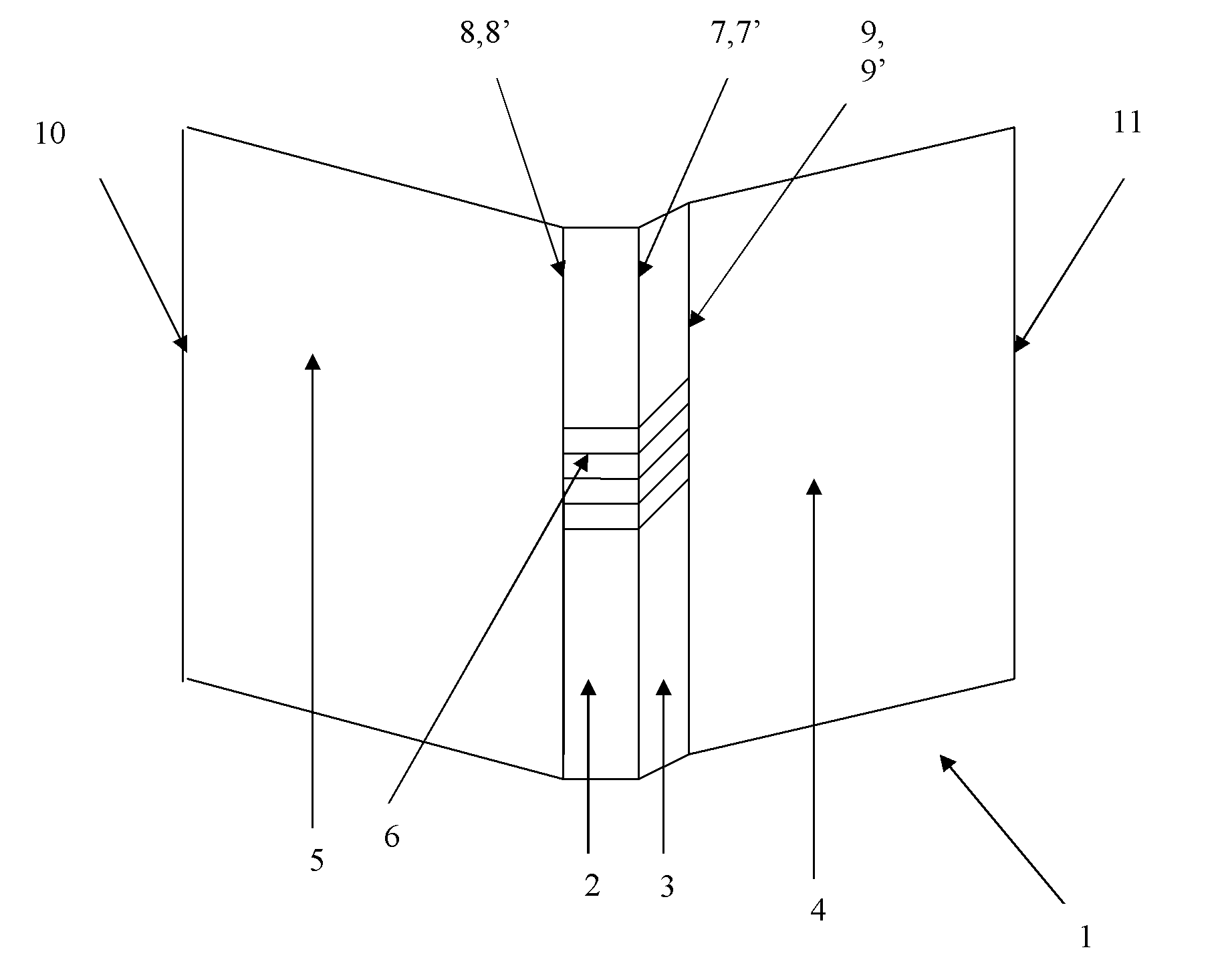
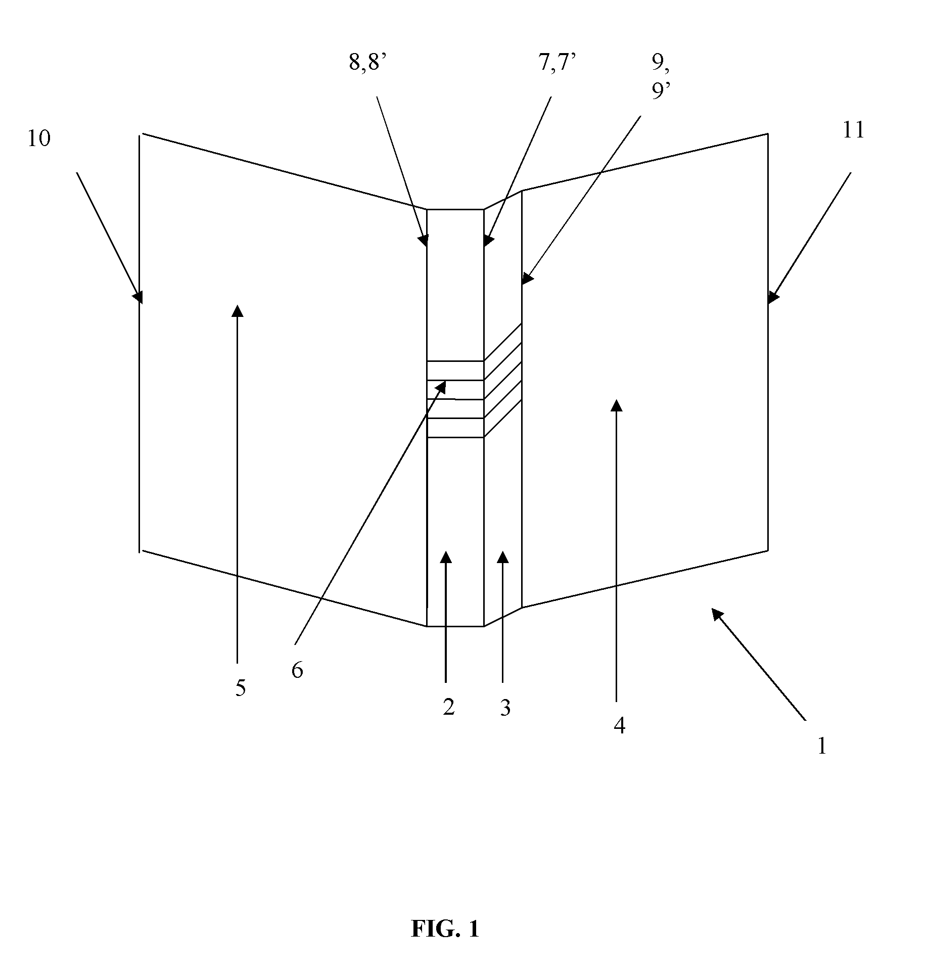
[0031]FIG. 1 illustrates a double hinged binder 1 including a spine 2, a front flange 3, a front cover 4, a rear cover 5, a label holder means 6 provided on the spine and a plurality of rings not shown disposed on the internal surface of the rear cover, in accordance with a preferred embodiment. Note that the label holder means can be configured to extend along the length of the spine and completely over area 3 (flange) and area 4 (front cover), depending upon the binder design configuration. The label holder 6 can be configured as a wrap-around label holder and may be implemented in a full-overlay fashion or partial small overlay configuration, depending upon design configurations. The label holder 6 illustrated in FIG. 1 is illustrated as a partial small overlay configuration...


PUM


Abstract

A double hinged binder includes a binder spine, a front flange, a front cover, a rear cover, each having a first and a second longitudinal edge, a label holder means provided on said binder spine and front flange and a plurality of rings disposed on the internal surface of the rear cover. The first longitudinal edge of the front flange is attached to the first longitudinal edge of the binder spine. The first longitudinal edge of the rear cover is attached to the second longitudinal edge of the binder spine. The first longitudinal edge of the front cover is attached to the second longitudinal edge of the front flange while the second longitudinal edge of the front cover is rotatably free. While the second longitudinal edge of the rear cover is rotatably free.

Description

FIELD OF THE INVENTION[0001]Embodiments to binders as utilized in home, school, offices, industrial and other environments. Embodiments also relate to a double hinged ring binder. More particularly, embodiments relate to a double hinged ring binder that promotes space economy, enables customized wrap around templates, is easy to use and incorporates a predetermined quick loading ring metal.BACKGROUND OF THE INVENTION[0002]Ring binders are generally used to hold punched sheets of paper by means of metal rings that run through holes punched into the sheets of paper. Ring binders conventionally known in the art have two to seven holes, which are used to maintain various stacks of paper. The more sheets of paper (thickness) the larger the capacity of the ring required to hold them.[0003]Binders conventionally known in the art suffer from various disadvantages, particularly when used for holding a thick stack of paper. Binders having a large capacity for holding larger paper stacks, for ...

Claims


Application Information

Patent Timeline
Patent Type & Authority Applications(United States)
IPC IPC(8): B42F13/00G09F3/18
CPCB42F13/0053G09F3/20B42F13/38
Inventor DAVIS, DOUGLAS B.MORIN, LARRY A.
Owner DAVIS DOUGLAS B
Why Eureka
Try Eureka