
Range image pixel matching method

Active Publication Date: 2013-10-17
IEE INT ELECTRONICS & ENG SA
View PDF5 Cites 17 Cited by
  • Summary
  • Abstract
  • Description
  • Claims
  • Application Information

AI Technical Summary

Benefits of technology

This patent describes a way to match high-resolution 2D images with low-resolution 3D images. The method involves using two range images, with the second range image having higher resolution than the first. This helps to accurately match the 3D image with the 2D image. The patent also suggests using a geometric configuration where the range image and the target image have a common grid structure, which reduces storage space by using a single lookup table. This makes it easier to match the 3D image with the 2D image.

Problems solved by technology

On the other hand, ToF cameras have much lower resolution than common 2D cameras and the range measurement is affected by noise.
A particular problem occurs if the reference frames of the two sensors are not co-centric, i.e. if the two cameras are displaced with respect to each other, which is typically the case.
These methods are numerically demanding and may fail in case of shadow effects, unstructured scenes, or periodic patterns.
Besides the fact that stereo vision techniques are numerically demanding, their application is rendered difficult, if not impossible, in case that the resolutions and the types of data of the two sensor data sets are different.

Method used


Image

  • Range image pixel matching method
  • Range image pixel matching method
  • Range image pixel matching method

Examples


Embodiment Construction

[0040]Introduction—Stereo Vision

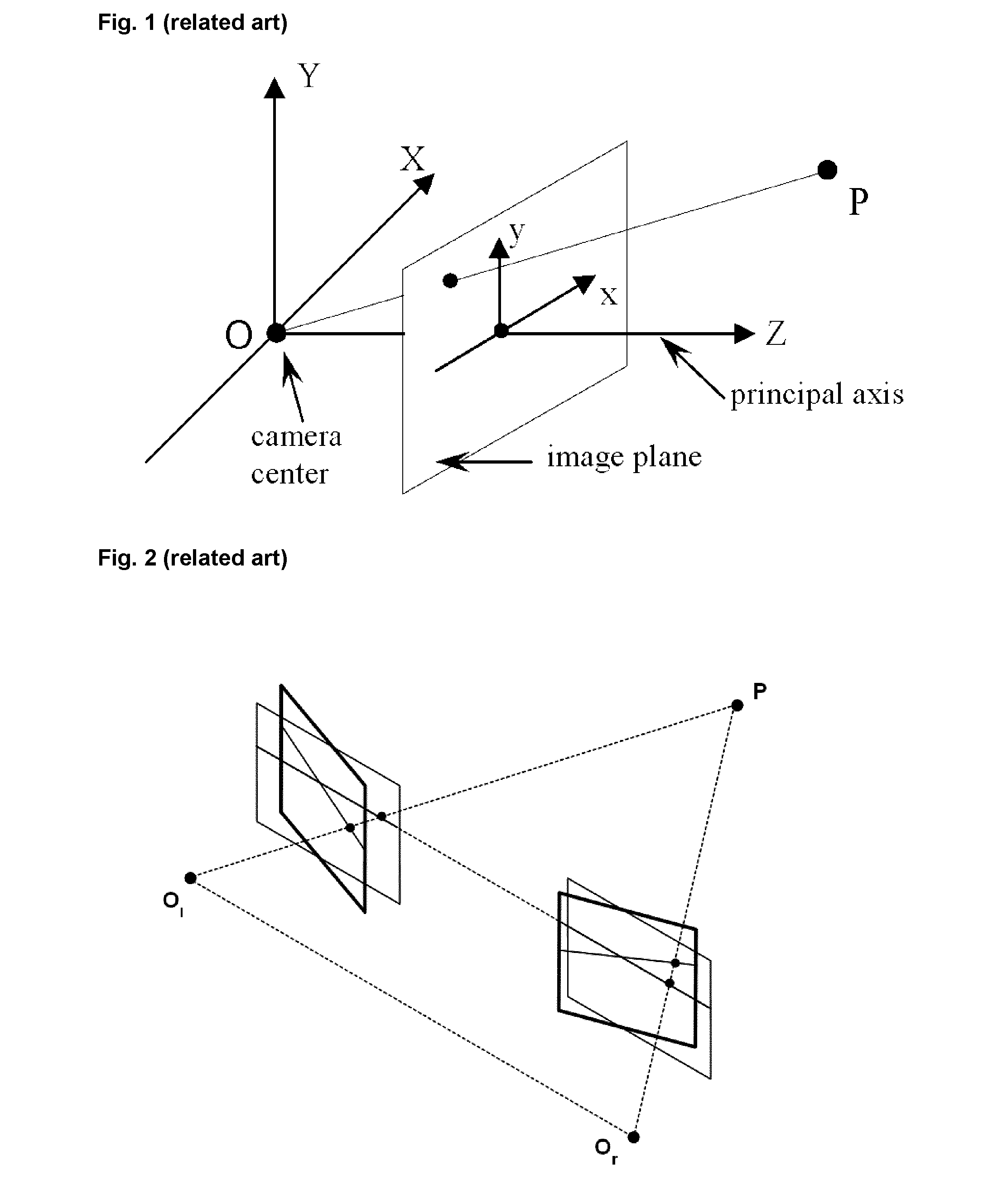
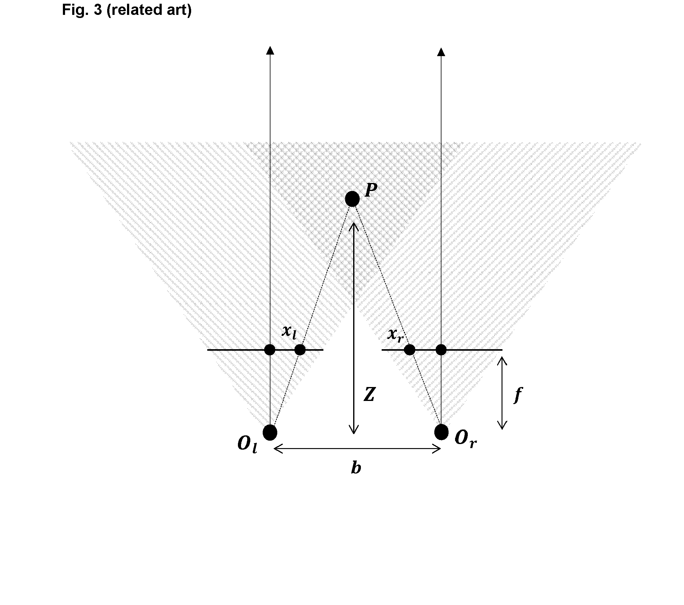
[0041]Matching the data of two 2D cameras onto each other is the main subject in the field of stereo vision. As this field is well established and developed with existing industrialized products, the state of the art is only briefly summarized with emphasis on the differences to the invention. For more details on stereo vision, the interested reader is referred to textbooks like [5,6].

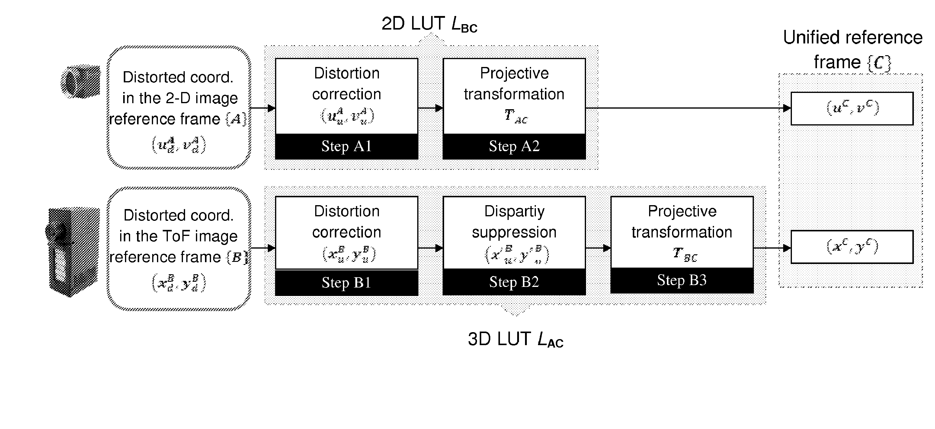
[0042]In the following we consider two sets of data IA(i,j) and IB(k,l) from the same scene, recorded in the camera reference frames A and B, respectively. The data are stored in the form of matrices where the indices i=1, . . . M, j=1, . . . , N, respectively k=1, . . . , K, l=1, . . . , L, refer to the pixels of the corresponding camera. The data types of IA and IB maybe digitalized gray or color values.

[0043]Solving the correspondence problem, that is finding pairs {(m,n),(k,l)} of pixels from both images that correspond to the same point in the scene is the main topi...


PUM


Abstract

A method for matching the pixels (10-1, 10-2) of a first range image of a scene (18) as seen from a first point of sight (14) with pixels (12-1, 12-2) of a second range image of the scene as seen from a second point of sight (16) comprises the following steps: providing the first range image as a grid of source pixels (10), on which the scene is mapped in accordance with a first projection associated with the first point of sight, wherein each source pixel has a point in the scene projected thereon in accordance with the first projection and has associated therewith a range value determined for that point in the scene; providing a grid of target pixels (12) for the second range image and a second projection associated with the second point of sight; and for each one of the target pixels, a) determining which source pixel would have the same point (P1, P2) in the scene projected thereon in accordance with the first projection as the target pixel would have projected thereon in accordance with the second projection if the imaged scene were a planar surface at a certain surface distance from the first point of sight; b) determining a depth coordinate of the point in the scene that the source pixel determined in step a) actually has projected thereon in accordance with the first projection; c) if the depth coordinate is greater than a threshold, which is itself greater than the surface distance, repeating steps a), b) and c) with an increased surface distance at step a) and an increased threshold at step c), and else associating the target pixel with the source pixel determined in step a).

Description

TECHNICAL FIELD[0001]The present invention generally relates to digital image processing, in particular transforming a range (or distance) image representing a scene as seen from a first point of sight into a range image representing the same scene as seen from a second, offset point of sight. The method according to the invention may e.g. be used for fusing a range image (3D image) and a conventional image (2D image) that have been acquired from different points of view.BACKGROUND ART[0002]In recent years, 3D cameras based on the Time-of-Flight (ToF) principle have become commercially available. Compared to 2D cameras, they measure, for each pixel, a radial distance of a point in the scene to the camera, while 2D cameras provide only a gray- or colour image of the scene. On the other hand, ToF cameras have much lower resolution than common 2D cameras and the range measurement is affected by noise. Therefore, there are many research and development activities ongoing that target fus...

Claims


Application Information

Patent Timeline
IPC IPC(8): G06T15/00
CPCG06T15/00G06T2207/10028G06T7/30
Inventor GARCIA BECERRO, FREDERICMIRBACH, BRUNO
Owner IEE INT ELECTRONICS & ENG SA
Learn More