Connectored cable and method for manufacturing connectored cable
Inactive Publication Date: 2013-10-17
FUJIKURA LTD
View PDF3 Cites 2 Cited by
Summary
Abstract
Description
Claims
Application Information
AI Technical Summary
This helps you quickly interpret patents by identifying the three key elements:
Problems solved by technology
Method used
Benefits of technology
Benefits of technology
The invention helps prevent damage to the part of the optical fiber where it connects to other parts. This is done by managing the extra length of the fiber so that it's less likely to move around in the connector.
Image
Click on the blue label to locate the original text in one second.
Reading with bidirectional positioning of images and text.
Examples
modified examples
First Modified Example
Example in Which Number of Loops of Optical Fiber 3 is Changed
[0213]In the foregoing embodiment, the extra length of the optical fiber 3 is managed by approximately two loops within the connector, and there were three bent portions within the connector. However, a method for managing the extra length of the optical fiber 3 within the connector is not limited to this. The extra length of the optical fiber 3 may also be managed by three or more loops within the connector.
[0214]FIG. 20 is a perspective view of the termination portion 12 of the camera-side connector 10 according to the first modified example as seen obliquely from below. It should be noted that the configuration and wiring on the upper side of the parent substrate 20 are the same as those of the above-described embodiment and therefore are omitted from the drawing.
[0215]In the first modified example, the extra length of the optical fiber 3 is managed by approximately three loops within the housing ...
second modified example
Example in Which Parent Substrate and Child Substrate are Not Separated
[0220]In the above-described embodiment, the parent substrate and the child substrate are separated from each other, which facilitates the connecting operation and the wiring operation of the optical fiber 3, the signal lines 5, and the power supply lines 6. However, if it is allowable to take time and effort for the connecting operation and the wiring operation, it is not necessary to separate the parent substrate and the child substrate from each other. In the case where the parent substrate and the child substrate are not separated from each other, the photoelectric conversion portion (the light-emitting portion 41 or the light-receiving portion 141) is installed on the parent substrate 20 by directly mounting it on the parent substrate 20.
[0221]FIG. 21 is a perspective view of the termination portion 12 of the camera-side connector 10 according to the second modified example as seen obliquely from above. As s...
third modified example
Example in Which Parent Substrate Does Not Have Recess
[0226]In the above-described embodiment, the parent substrate has the recess formed thereon, and the optical fiber 3 is wired from the lower side to the upper side of the parent substrate through the recess. However, the parent substrate may not have the recess.
[0227]FIG. 22 shows the termination portion 112 of the grabber-side connector 110 according to the third modified example as seen obliquely from above. As shown in this drawing, in the third modified example, the recess 124 is not formed on the right edge of the parent substrate 120. Moreover, in the third modified example, the optical fiber 3 is wired from the lower side to the upper side, passing the outer side of the right edge of the parent substrate 120.
[0228]In the third modified example, it is necessary to provide a space that is approximately equal to the diameter of the optical fiber between the inner surface of the housing 111 and the right edge of the parent sub...
PUM
Property
Measurement
Unit
Angle
aaaaa
aaaaa
Abstract
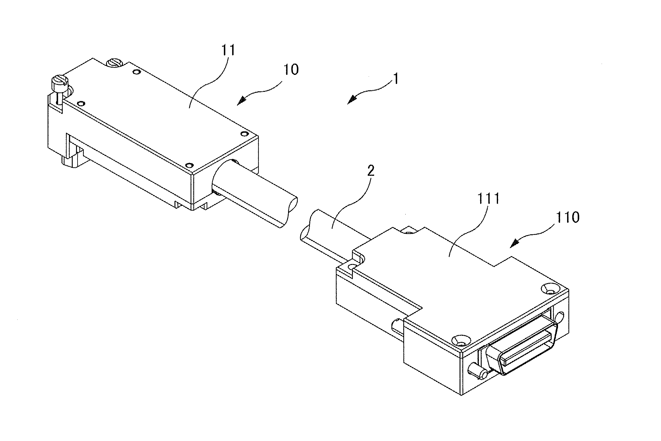
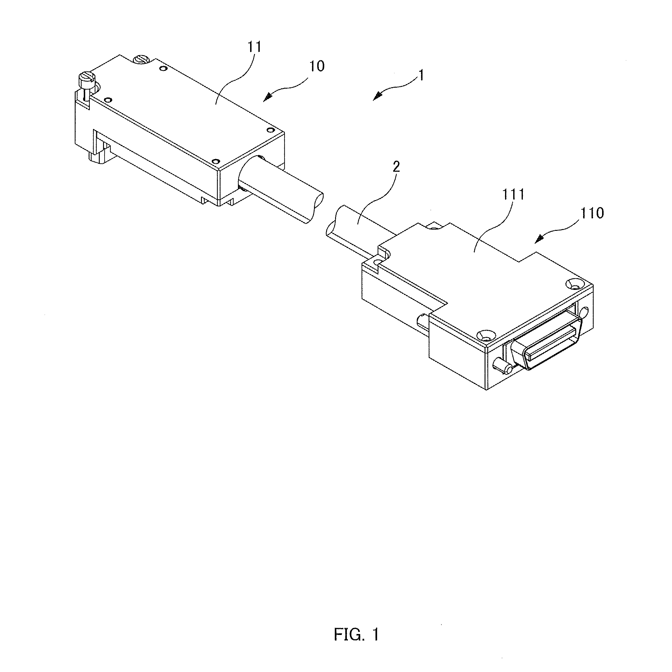
A connectored cable including: a cable having an optical fiber for transmitting an optical signal; and a connector that accommodates a substrate on which a photoelectric conversion portion that is optically coupled to an end face of the optical fiber is installed, and in which the optical fiber is wired so that at least three bent portions are formed, the orientation of the optical fiber in a front-rear direction being changed, the optical fiber being bent into a U shape at each of the bent portions, and so that one of two bent portions on a front side is located on a down side of the substrate and the other bent portion on the front side is located on an up side of the substrate, the front-rear direction referring to a direction in which the cable extends from the connector, a rear side referring to a side in which the cable extends as seen from the connector, the front side referring to an opposite side of the side in which the cable extends, the up side referring to a side of the photoelectric conversion portion as seen from the substrate, the down side referring to an opposite side of the side of the photoelectric conversion portion.
Description
TECHNICAL FIELD[0001]The present invention relates to a connectored cable and a method for manufacturing the connectored cable.BACKGROUND ART[0002]To perform optical transmission between devices, for example, it is possible to use a scheme as follows: a photoelectric conversion portion that performs conversion between electrical and optical signals is provided in each device, an optical cable is connected to the photoelectric conversion portions with optical connectors, and optical signals is sent and received through this optical fiber cable.[0003]This scheme has a problem that any dirt or foreign matter deposited on the optical connectors may degrade signals. Moreover, in this scheme, an optical fiberprocessing portion and a photoelectric conversion portion need to be provided in a device. Thus, a connectored cable has been proposed in which photoelectric conversion portions are provided on the connector side (PTL 1).CITATION LISTPatent Literature[0004][PTL 1] JP H5-226027ASUMMAR...
Claims
Application Information
Patent Timeline
Application Date:The date an application was filed.
Publication Date:The date a patent or application was officially published.
First Publication Date:The earliest publication date of a patent with the same application number.
Issue Date:Publication date of the patent grant document.
PCT Entry Date:The Entry date of PCT National Phase.
Estimated Expiry Date:The statutory expiry date of a patent right according to the Patent Law, and it is the longest term of protection that the patent right can achieve without the termination of the patent right due to other reasons(Term extension factor has been taken into account ).
Invalid Date:Actual expiry date is based on effective date or publication date of legal transaction data of invalid patent.

