Micrometer

Active Publication Date: 2013-10-24
MITUTOYO CORP
View PDF9 Cites 12 Cited by
  • Summary
  • Abstract
  • Description
  • Claims
  • Application Information

AI Technical Summary

Benefits of technology

[0024]With this arrangement, since the deformation detecting section is provided by the strain gauge and the strain gauge is disposed in the inner sleeve to whic

Problems solved by technology

Accordingly, repeatability of the micrometer

Method used


Image

  • Micrometer
  • Micrometer
  • Micrometer

Examples


Embodiment Construction

)

[0032]Exemplary embodiment(s) of the invention will be described below with reference to the attached drawings.

Arrangement of Digital Micrometer

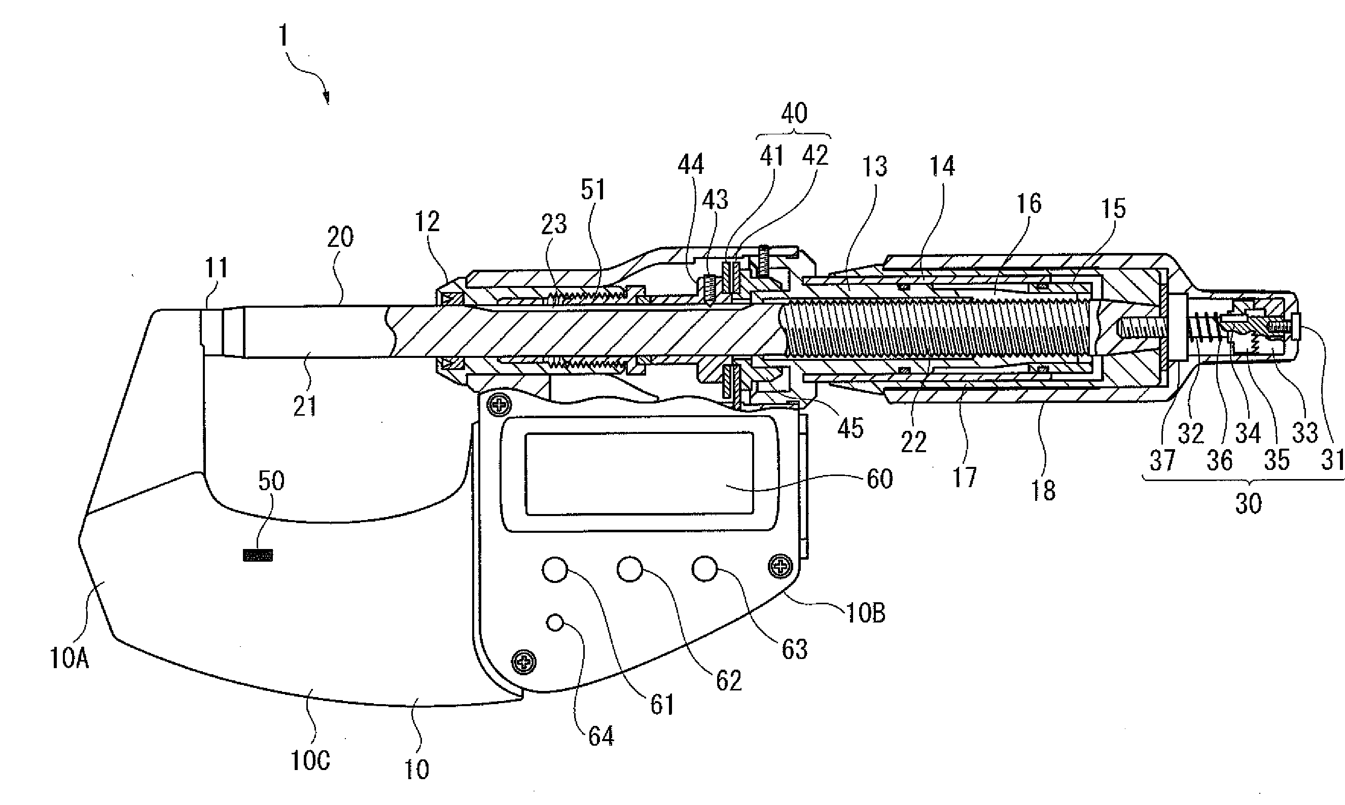
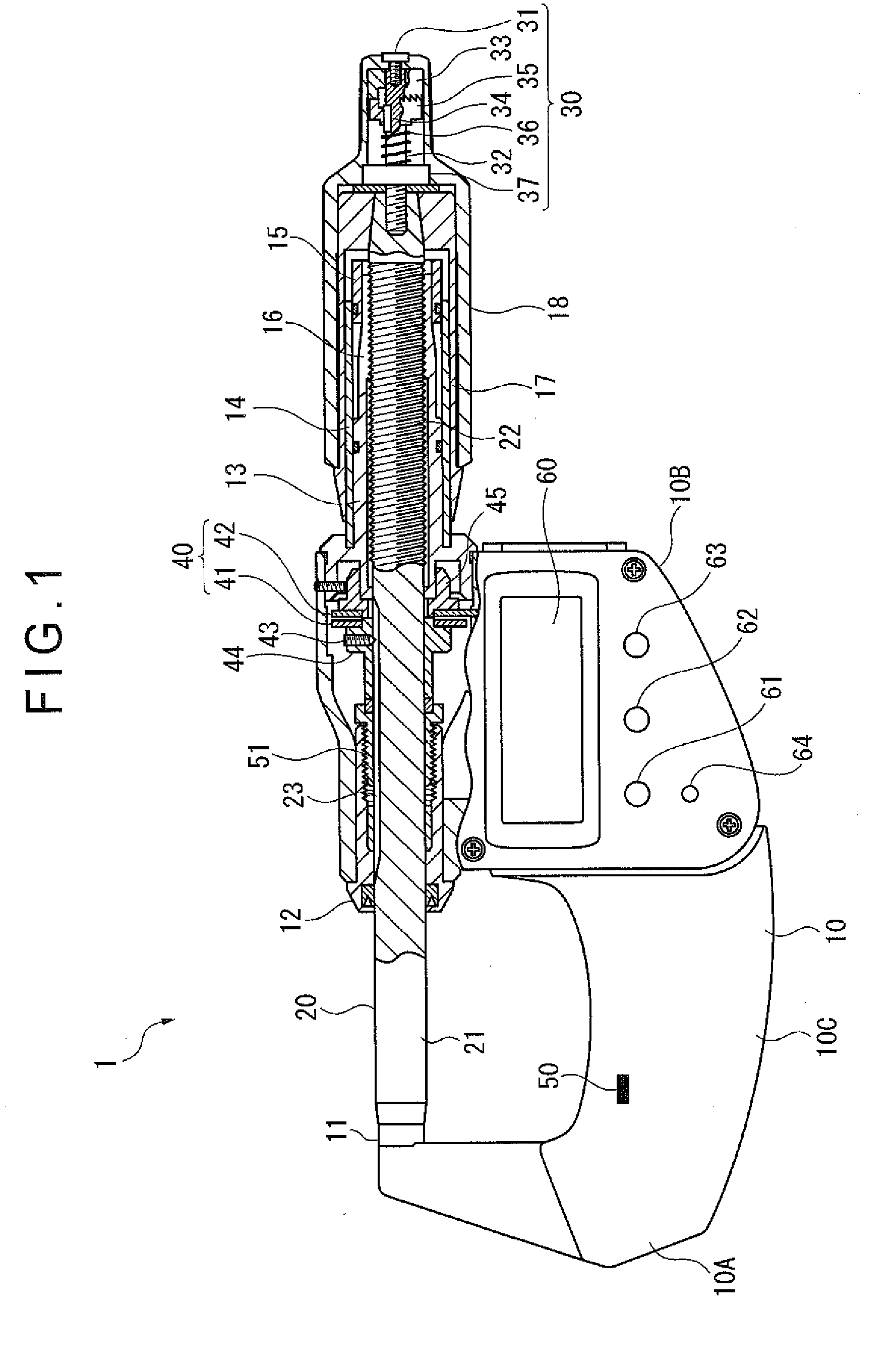
[0033]FIG. 1 is a partial cross section showing a digital micrometer according to an exemplary embodiment of the invention. In FIG. 1, a digital micrometer 1 includes: a substantially U-shaped frame 10; an anvil 11 fixed on an inner surface of one end of the frame 10; a spindle 20 that is provided to the other end of the frame 10 and is advanced and retracted relative to the anvil 11 while being axially displaced; an encoder 40 that is provided inside the frame 10 and detects a displacement of the spindle 20; and a display 60 that displays a measurement value obtained by processing a detection value detected by the encoder 40. The spindle 20 includes a spindle body 21 and a threaded shaft 22 which are in alignment. A cross-sectionally V-shaped key groove 23 is axially formed on an outer circumference of the spindle body 21. The threaded sha...


PUM


Abstract

A micrometer includes: a frame; an anvil; a spindle; an encoder; a display; a strain gauge that detects a deformation of the frame; a storage that stores a change amount of the detection value (a displacement of the spindle detected by the encoder) per a unit deformation detected by the strain gauge, as a compensation factor; and a compensator that compensates the detection value based on a difference between a zeroset-time deformation that is detected by the strain gauge when a command for zeroset is given and a measurement-time deformation that is detected by the strain gauge in measurement, and based on the compensation factor stored in the storage.

Description

[0001]The entire disclosure of Japanese Patent Applications No. 2012-097497 filed Apr. 23, 2012 is expressly incorporated by reference herein.BACKGROUND OF THE INVENTION[0002]1. Field of the Invention[0003]The present invention relates to a micrometer for measuring a dimension or the like of an object to be measured based on an axial displacement of a spindle.[0004]2. Description of Related Art[0005]A micrometer using a lead screw has been known as one of displacement measuring instruments.[0006]The micrometer includes: a U-shaped frame; an anvil fixed to one end of the frame; a spindle that is screwed to the other end of the frame and is advanced and retracted relative to the anvil; an encoder that detects a displacement of the spindle; and a display that displays a measurement value obtained by processing a detection value detected by the encoder.[0007]Among the micrometers, there has been known a micrometer including a constant pressure device for stabilizing a measurement force ...

Claims


Application Information

Patent Timeline
IPC IPC(8): G01B3/18
CPCG01B3/18
Inventor TSUJI, SHOZABURO
Owner MITUTOYO CORP
Why Eureka
Try Eureka