Portable baking oven

a portable oven and oven body technology, applied in the field of ovens, can solve the problems of not efficiently and evenly concentrating heat, pizzas to be either overdone on the top or burned on the bottom, and the temperature rise at the top of pizzas is still insufficiently high to accelerate baking, so as to enhance the ability of the oven to accelerate baking

Active Publication Date: 2013-10-24
CHARCOAL COMPANION LTD
View PDF18 Cites 92 Cited by
  • Summary
  • Abstract
  • Description
  • Claims
  • Application Information

AI Technical Summary

Benefits of technology

[0007]The invention is directed to a baking oven for a pizza or other suitable food items, for example cookies, which circulates heat generated in a heating chamber in the base of the oven up into a top baking chamber above a heating plate supporting the food item being baked. The oven efficiently redirects the heat circulated to the baking chamber back down onto the food item resting on the heating plate so that the top of the food item is evenly heated. The efficient redirection of heat is accomplished without trapping moisture in the baking chamber.
[0010]In use, heat generated in the base of the baking oven is circulated to the baking chamber formed by the top cover through the air passageway or passageways provided around the heating plate. The heat circulated to the baking chamber is redirected to and over the top of a food item resting on the heating plate by the well-positioned heat reflector structure of the top cover. In the preferred embodiment, moisture emitted by the food item can be allowed to escape through the heat reflector structure where it can be vented from the oven through a moisture vent located in the cover above the reflector structure. It is also noted that, in addition to venting moisture, the moisture vent will create an air flow through the baking chamber. This air flow produces a chimney effect which will elevate the temperature within the baking chamber, thereby enhancing the ability of the oven to accelerate the baking of the top of the food item on the heating plate.
[0011]In another and separate aspect of the invention, a front access opening can be provided in the top cover of the oven to allow food items such as an uncooked pizza to be placed on the heating plate of the oven once it is preheated. An extender brim can be provided on top of the front access opening to inhibit heat loss through the front access opening. Preferably, the heat reflector structure is positioned near the top edge of the front access opening to minimize the spacing between the heat reflector structure and the food items on the food item heating plate. Means can be provided for allowing more of the heat produced in the heating chamber to circulate up into the baking chamber near the front access opening to compensate for heat loss through the front access opening. Examples of such means include differential sizing of air passageways around the heating plate or providing a heat source that produces more heat below the front access opening of the oven.

Problems solved by technology

The problem with such conventional ovens is that, due to the substantial temperature differences between the pizza stone and the air above the pizza, the bottom of the pizza bakes more quickly than the top, causing the pizza to either be underdone on the top or overdone or burnt on the bottom.
However, the approach disclosed in the '833 patent has disadvantages.
The dome-shaped cover traps heat circulated up from the heat source below the pizza stone, and does not efficiently and evenly concentrate the heat where it needs to be, namely, across the top of the pizza.
With a dome shaped cover it is found that the temperature rise at the top of the pizza is still insufficiently high to accelerate baking of the top of the pizza enough to keep up with the baking of the bottom of the pizza.
A second disadvantage of the dome shaped cover as taught by U.S. Pat. No. 5,365,833 is that the cover traps moisture given off by the pizza, which could cause the top of the pizza to become soggy and under-cooked.

Method used


Image

  • Portable baking oven
  • Portable baking oven
  • Portable baking oven

Examples


Embodiment Construction

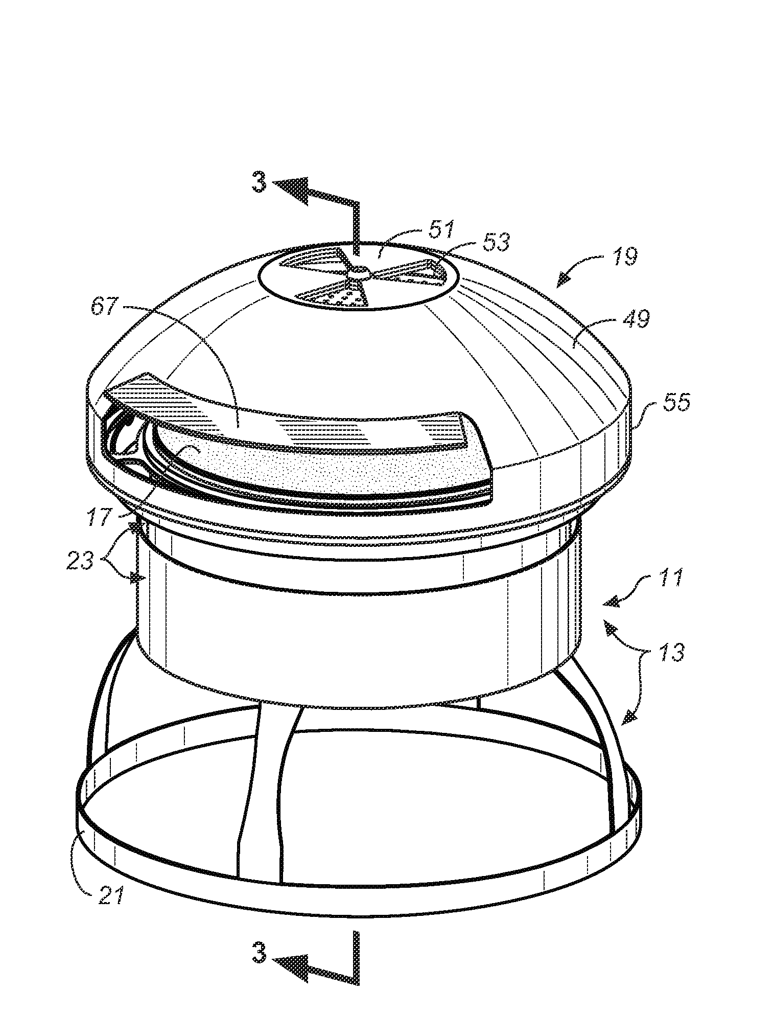
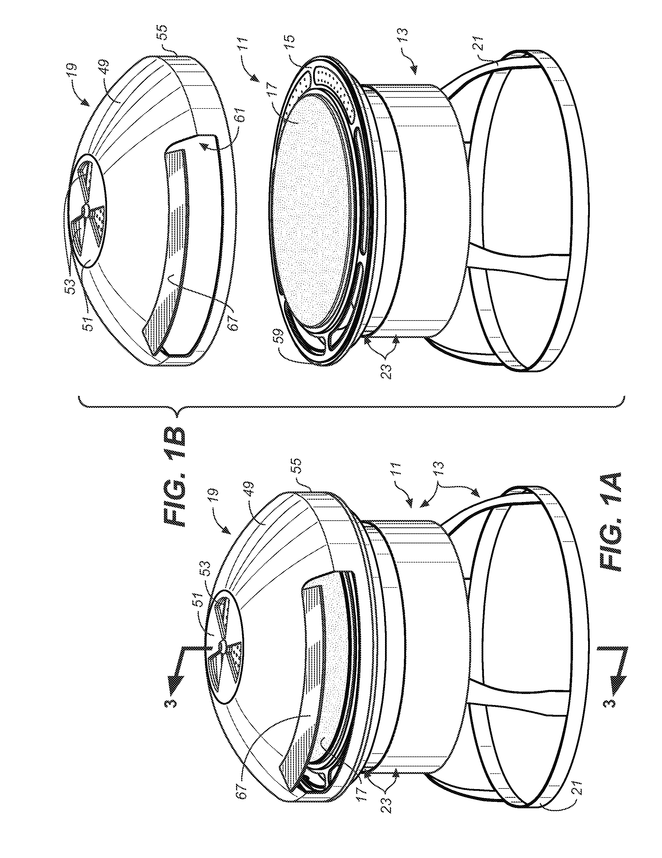
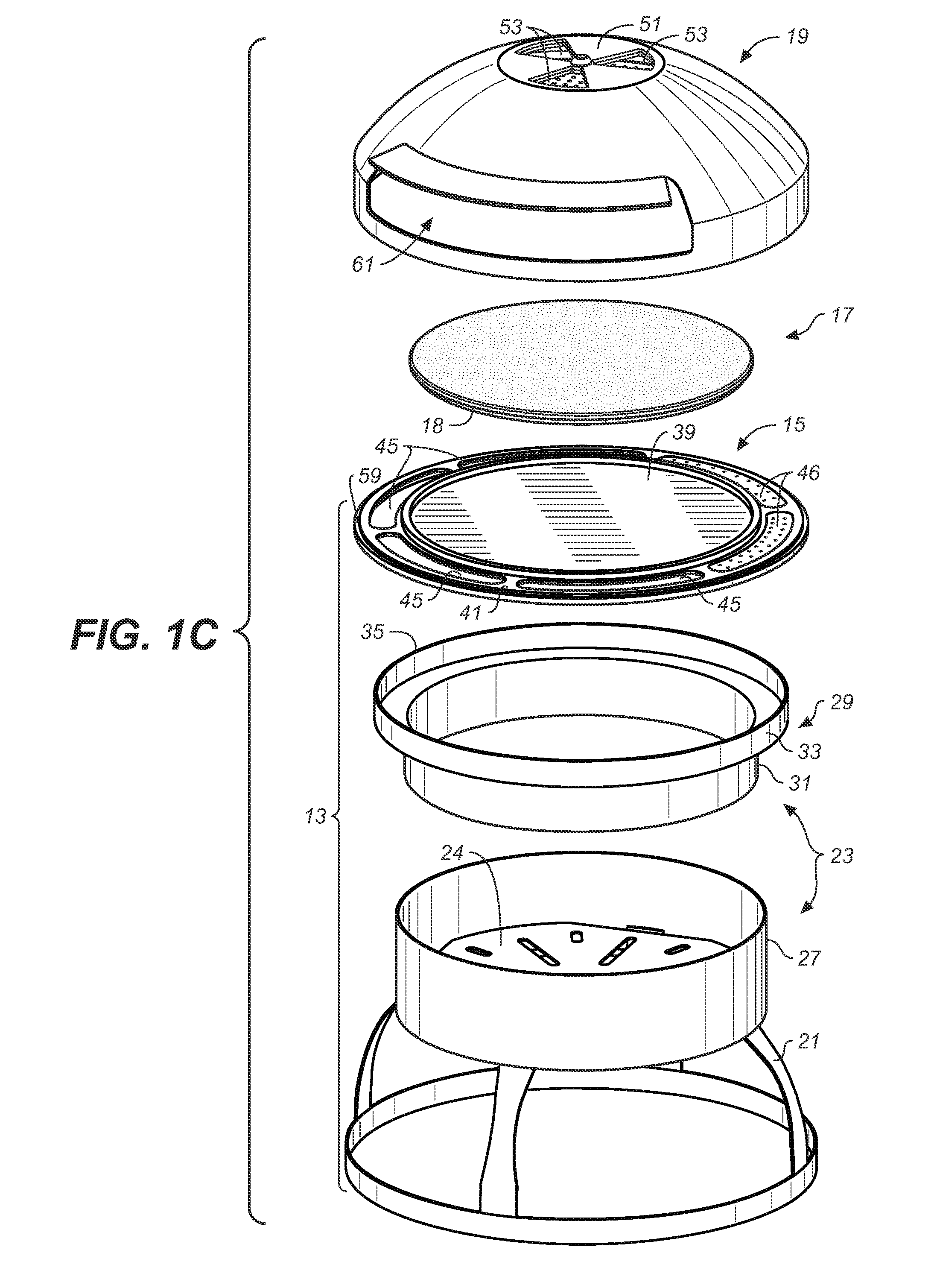
[0030]Referring now to the drawings, FIGS. 1-8 illustrate a first embodiment of a portable baking oven in accordance with the invention. The basic elements of the baking oven, denoted by the numeral 11, are a base 13 having a heating chamber 14 (see FIG. 3), a food item heating plate 17 and a top cover 19 having novel heat reflecting capabilities as hereinafter described. When placed on the base, the top cover forms an upper baking chamber 20 (again see FIG. 3) above the heating plate, which also as hereinafter described is in thermal communication with the heating chamber of the base.

[0031]The base 13 has means for supporting the oven's heating plate above its heating chamber 14. In this illustrated embodiment, the heating plate support means is in the form of support plate 15 located at the top portion of the base; however, as later described, the heating plate could be supported over the base's heating chamber by other structural means.

[0032]The oven base 13 in this embodiment is...


PUM


Abstract

A portable baking oven for a pizza or other food item includes a food item heating plate, a base having a heating chamber, and a top cover having a moisture vent and a heat reflector structure extending across the inside of said top cover. When placed on said base, the top cover forms a baking chamber above the heating plate. Heat produced in the base's heating chamber circulates up through air passageways in the base into the baking chamber above the food item heating plate. This circulated heat is reflected back down toward the food item heating plate by the top cover's heat reflecting structure to accelerate baking of the top of a food item placed on the heating plate. The top cover's moisture vent can be located above the heat reflector structure in the top cover, and openings can be provided in the heat reflector structure which allow moisture emitted by a food item being baked in the oven to pass through the reflector structure and out through the top cover moisture vent.

Description

CROSS-REFERENCE TO RELATED APPLICATIONS [0001]The application claims the benefit of U.S. Provisional Patent Application No. 61 / 636,191 filed Apr. 20, 2012, which is incorporated herein by reference.BACKGROUND OF INVENTION[0002]The present invention generally relates to ovens used for cooking and baking and more particularly to ovens that are portable and that are particularly adapted to baking pizzas and other flat food items.[0003]Portable ovens for baking pizzas are widely known. Typically, such ovens include a heat source below a flat stone or ceramic plate, often called a “pizza stone,” on which the pizza is supported. The pizza stone has a high thermal mass and evenly and efficiently distributes the heat to the bottom of the pizza so that the bottom of the pizza is evenly baked. The problem with such conventional ovens is that, due to the substantial temperature differences between the pizza stone and the air above the pizza, the bottom of the pizza bakes more quickly than the ...

Claims


Application Information

Patent Timeline
Patent Type & Authority Applications(United States)
IPC IPC(8): A47J37/01
CPCA47J37/01A47J37/0623A47J37/0658F24B1/003
Inventor KROLICK, ROBERT S.SHAPIRO, SANFORDBOROVICKA, CORY THOMAS
Owner CHARCOAL COMPANION LTD
Why Eureka
Try Eureka