Composite sandwich mirror panel useful in concentrated solar power systems

a solar power system and sandwich mirror technology, applied in the field of mirror panel assembly, can solve the problems of reduced bending stiffness, increased relative radial motion between the skins, and increased bending stiffness, and achieve the effect of low bending stiffness and high shear stiffness

Inactive Publication Date: 2018-11-01
SOLARRESERVE TECH
View PDF7 Cites 0 Cited by
  • Summary
  • Abstract
  • Description
  • Claims
  • Application Information

AI Technical Summary

Benefits of technology

[0023]Because of the relatively close spacing of the core elements used to couple composite skins, the use of thinner glass as a top skin may be feasible. This can help reduce the panel assembly weight further and can result in better mirror reflectivity. Note, however, that if the glass were too thin, the shear stiffness of a panel may be lower than desired. At some thickness threshold, a minimum stiffness required to resist gravity or wind loads may be an important design variable to select a suitable thickness of a glass panel. A significant advantage of the present invention is that core elements may be used to tune stiffness, including reducing or increasing stiffness, to allow thinner glass sheets to be more easily incorporated into designs.
[0024]In one aspect, the present invention relates to an articulating heliostat comprising a mirror panel assembly, wherein the mirror panel assembly comprises:
[0025](a) a bottom component comprising (i) an upper surface (ii) a lower surface and (iii) at least one reference site, and;
[0026](b) a top component that is spaced apart from the bottom component and that has a bottom surface and a reflective upper surface effective to redirect incident sunlight; and
[0027](c) a core component interposed between the bottom component and the top component and comprising a plurality of spaced apart core elements that couple the bottom component to the top component in a spaced apart fashion, wherein the core elements are provided in a manner such that at least a portion of the mirror panel assembly has a relatively high shear stiffness proximal to the reference site and a relatively low shear stiffness distal from the reference site.
[0028]In another aspect, the present invention relates to a composite panel assembly, comprising:

Problems solved by technology

However, further away from the attachment point, the relative radial motion between the skins tends to be greater when temperature changes.
At first glance, this may appear to be problematic.
However, bending stiffness may decrease as a function of distance from the attachment point without resulting in unduly higher deflection.

Method used


Image

  • Composite sandwich mirror panel useful in concentrated solar power systems
  • Composite sandwich mirror panel useful in concentrated solar power systems
  • Composite sandwich mirror panel useful in concentrated solar power systems

Examples


Embodiment Construction

[0072]The present invention will now be further described with reference to the following illustrative embodiments. The embodiments of the present invention described below are not intended to be exhaustive or to limit the invention to the precise forms disclosed in the following detailed description. Rather a purpose of the embodiments chosen and described is so that the appreciation and understanding by others skilled in the art of the principles and practices of the present invention can be facilitated.

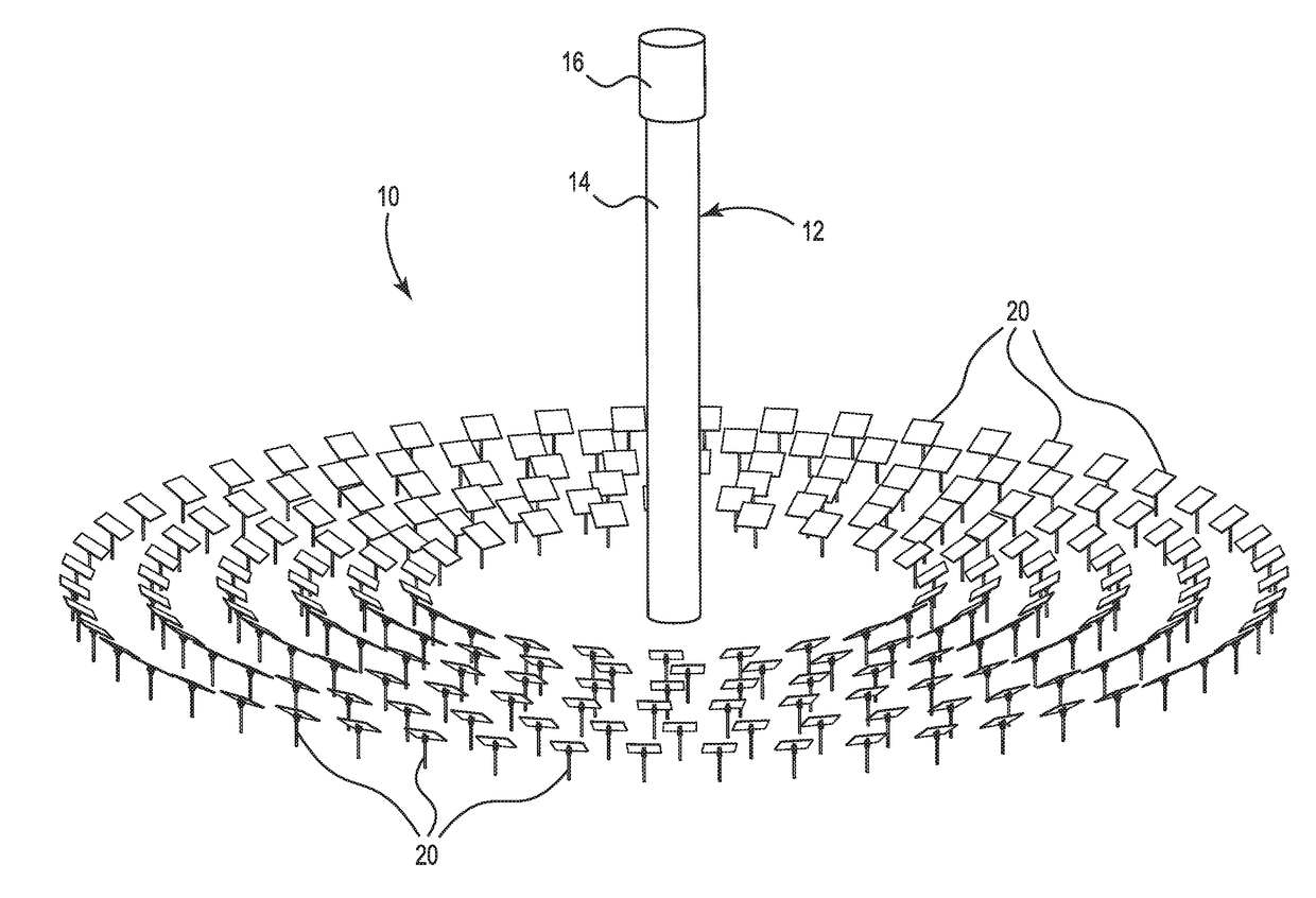
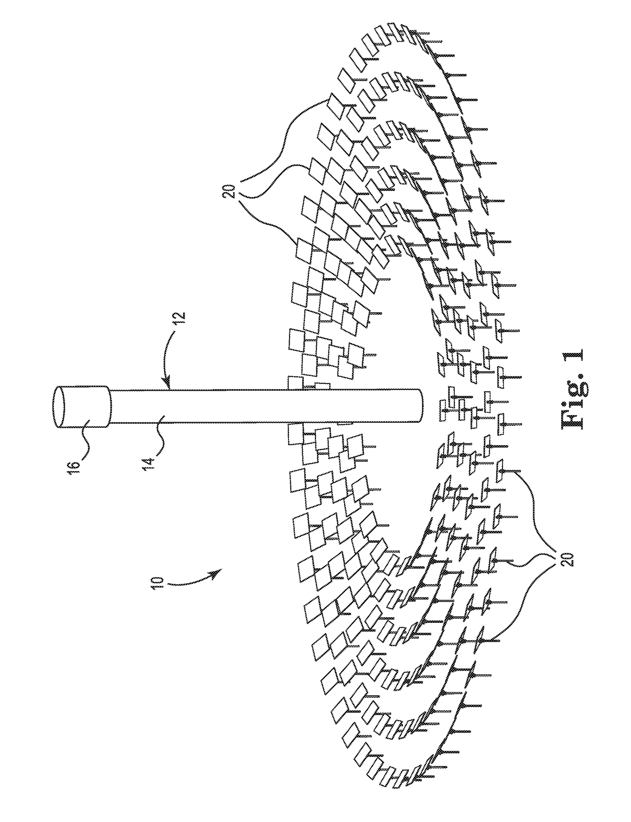
[0073]Referring to the figures and in particular FIG. 1, which schematically illustrates a concentrating solar energy system 10 that incorporates principles of the present invention. System 10 includes a central tower 12 including a mast 14 and a target region 16 at the top of the mast. A field of heliostats 20 is deployed around central tower 12. The heliostats 20 redirect and concentrate incident sunlight onto target region 16. If system 10 embodies a photovoltaic solar power sys...


PUM


Abstract

The present invention provides strategies for mitigating the deleterious effects of differential thermal expansion in composite panel structures. The principles of the present invention are particularly useful in the field of concentrating solar power. The principles of the present invention can be used in CSP applications to make composite mirror panel structures with improved characteristics for accommodating differential thermal expansion between components of the composite. Significantly, the composite mirrors structures can still be securely attached to other heliostat components such as a drive mechanism while still having the ability to accommodate differential thermal expansion between the skins of a composite mirror panel helps to limit energy losses due to slope errors.

Description

PRIORITY[0001]This application claims the benefit of U.S. Provisional Patent Application Ser. No. 62 / 153,723, filed on Apr. 28, 2015; U.S. Provisional Patent Application Ser. No. 62 / 153,716, filed on Apr. 28, 2015; and U.S. Provisional Patent Application Ser. No. 62 / 211,376, filed on Aug. 28, 2015, which are incorporated herein by reference in their entirety for all purposes.FIELD OF THE INVENTION[0002]The present invention is an improved mirror panel assembly used for reflecting light to a target. More specifically, this mirror panel approach is intended for use in applications related to the field of Concentrated Solar Power (CSP), such as for heliostats and solar troughs, among others.BACKGROUND[0003]Solar power plants or other systems that collect and concentrate solar energy onto one or more centralized targets are well known in the art. The concentrated solar energy often is used to directly or indirectly produce electricity and / or heat. Direct conversion, often referred to as...

Claims


Application Information

Patent Timeline
Patent Type & Authority Applications(United States)
IPC IPC(8): G02B7/18G02B7/183G02B5/08G02B19/00F24S20/20F24S20/30F24S23/70F24S50/20
CPCG02B7/181G02B7/183G02B5/085G02B19/0019G02B19/0042H02S40/22F24S2020/11F24S23/82F24S30/455Y02E10/47Y02E10/52F24S2020/15
Inventor GREGORY, CHRISTIANGATES, GREGORY
Owner SOLARRESERVE TECH
Why Eureka
Try Eureka