Switching power supply device

Active Publication Date: 2013-10-24
FUJI ELECTRIC CO LTD
View PDF6 Cites 13 Cited by
  • Summary
  • Abstract
  • Description
  • Claims
  • Application Information

AI Technical Summary

Benefits of technology

[0012]According to the switching power supply device with the heretofore described configuration, as the jitter width Δf for the switching power supply frequency fs is determined avoiding the sideband width BW of the AM radio reception frequency to be received, and the jitter of the power supply frequency fs is controlled on the sideband side of the AM radio reception frequency that does not include the power supply harmonic component, it is possible to avoid interference between the power supply noise frequency and AM radio frequency bandwidth, and thus possible to avoid impeding the reception of the AM radio broadcast.
[0013]Moreover, as it is possible to spread the power spectrum of the power supply noise freque

Problems solved by technology

It is undeniable that, in a switching power supply device, high frequency power supply noise (electromagnetic interference noise; EMI noise) is generated accompanying a switching operation in a semiconductor switching element.
In the event that the frequency of this kind of power supply noise overlaps an AM radio frequency bandwidth, it is a cause of hindering the reception of the AM radio broadcast (AM reception impedance).
However, even when reducing power supply noise using the switching frequency jitter control technology introduced in JP-A-2003-153526, impeding of

Method used


Image

  • Switching power supply device
  • Switching power supply device
  • Switching power supply device

Examples


Embodiment Construction

[0020]Hereafter, referring to the drawings, a description will be given of a switching power supply device according to an embodiment of the invention.

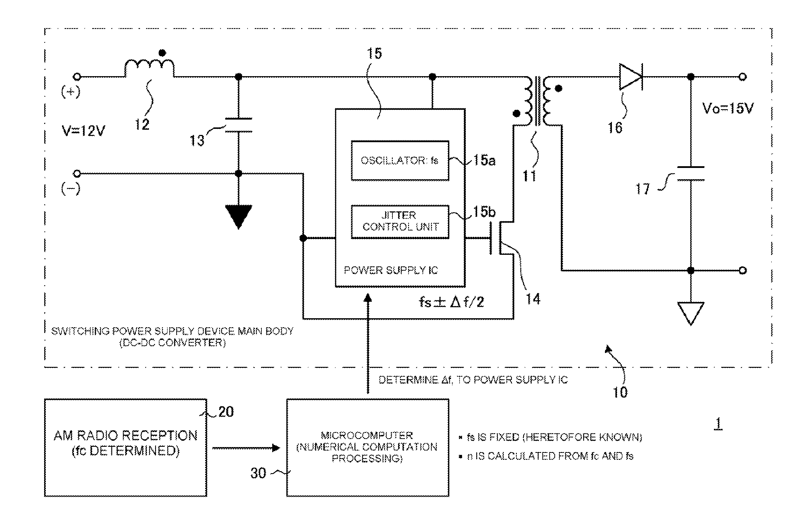
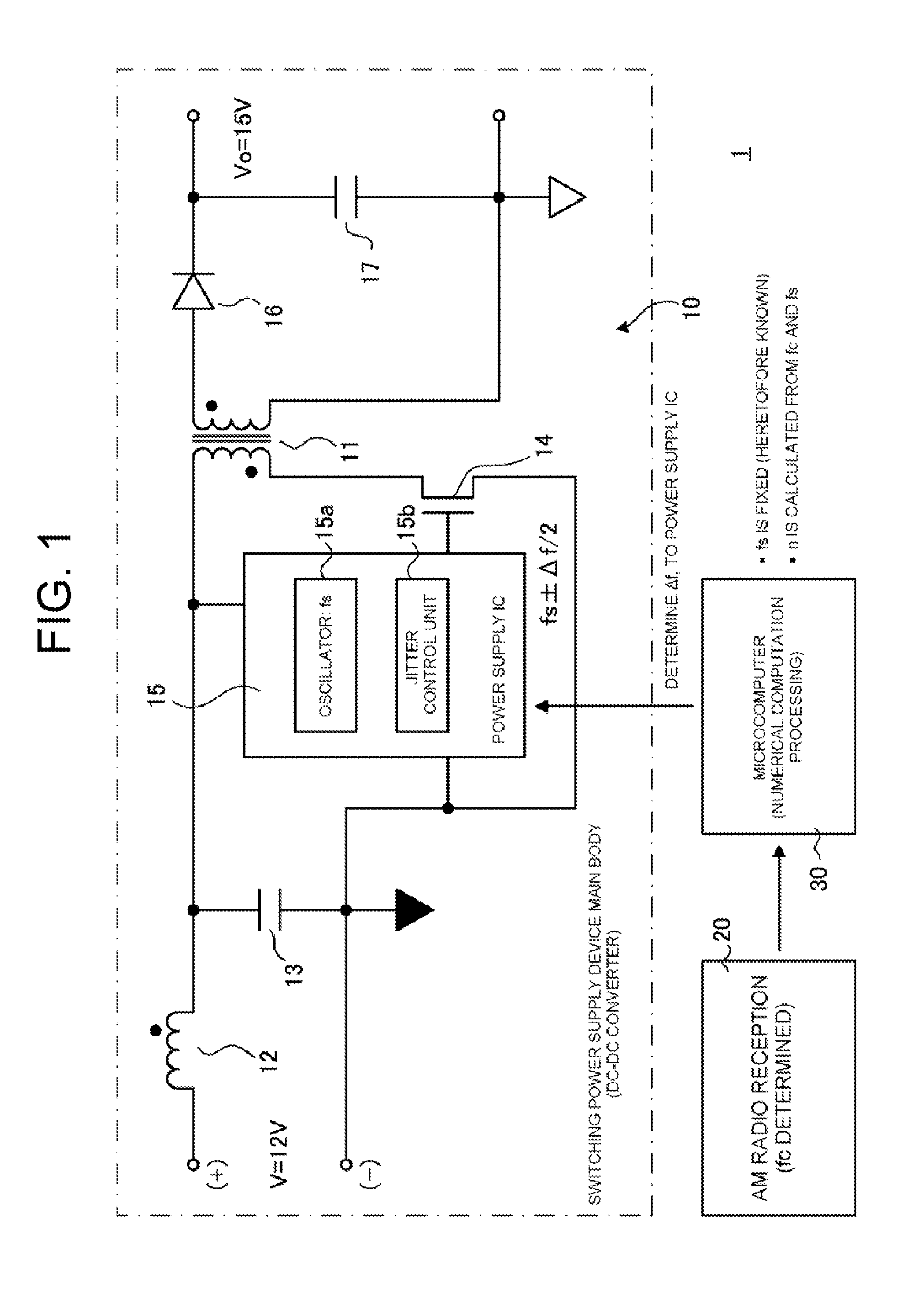
[0021]FIG. 1 is a schematic diagram showing an overall configuration of a switching power supply device 1, wherein reference sign 10 indicates a switching power supply device main body (a DC-DC converter). The switching power supply device main body 10 is for mounting in a vehicle, and bears a role of switching direct current power (12V) supplied from a battery (not shown) mounted in the vehicle at a predetermined power supply frequency fs, applying the power to an insulating transformer 11, rectifying and smoothing alternating current power extracted from the secondary side of the insulating transformer 11, and supplying direct current voltage to each kind of electronic instrument (vehicle-mounted instrument) mounted in the vehicle together with the switching power supply device main body 10.

[0022]Specifically, the direct current pow...


PUM


Abstract

A switching power supply device that can reduce power supply noise includes a switching power supply device main body that switches a semiconductor switching element at a power supply frequency fs, and supplies power to an electronic instrument such as an AM radio receiver. The switching power supply device detects an AM radio reception frequency fc and a power supply harmonic component that interferes with the AM radio reception frequency fc. Further, the switching power supply device determines, in a sideband of the AM radio reception frequency fc on a side that does not include the power supply harmonic component, a jitter width Δf for the power supply frequency fs, avoiding a bandwidth BW of the AM radio reception frequency fc, controlling the jitter of the power supply frequency fs in the jitter width Δf, and switching the semiconductor switching element at a frequency of [fs±Δf/2].

Description

BACKGROUND OF THE INVENTION[0001]1. Technical Field[0002]The present invention relates to a switching power supply device such that an impeding of the reception of an AM radio broadcast due to power supply noise is avoided, and a reduction in power supply noise is achieved.[0003]2. Related Art[0004]It is undeniable that, in a switching power supply device, high frequency power supply noise (electromagnetic interference noise; EMI noise) is generated accompanying a switching operation in a semiconductor switching element. In the event that the frequency of this kind of power supply noise overlaps an AM radio frequency bandwidth, it is a cause of hindering the reception of the AM radio broadcast (AM reception impedance). Therefore, to date, it has been proposed that reception impedance is avoided by demodulating an AM signal from a sideband on a side of an AM radio receiver in which high frequency power supply noise from the switching power supply device is not included (for example, ...

Claims


Application Information

Patent Timeline
IPC IPC(8): H02M3/335
CPCH02M3/335H02M1/44
Inventor NISHIJIMA, KENICHI
Owner FUJI ELECTRIC CO LTD
Why Eureka
Try Eureka