Interlocking construction systems and methods

a construction system and interlocking technology, applied in the direction of construction, covering/lining, ways, etc., can solve the problems of uneven surface, damage to pavers and occasionally plow blades, and less than pleasing appearance and not desirable

Inactive Publication Date: 2013-10-24
HETTRICH HANSL
View PDF4 Cites 10 Cited by
  • Summary
  • Abstract
  • Description
  • Claims
  • Application Information

AI Technical Summary

Benefits of technology

[0011]In accordance with another aspect, the peripheral edge can define a repeating pattern along at least one edge of the paver. The resulting top surface of the paver can be rectangular in shape. By way of further example, the top surface of the paver can be hexagonal, square or triangular in shape, among others. Preferably, the peripheral edge resembles a continuous helical pattern along at least two contiguous sides of the paver. The disclosure also provides a related method of paving a surface, comprising providing pavers with interlocking edges that prevents relative vertical displacement of the pavers once the pavers are installed, as described herein, and installing the pavers. If desired, an edging member with a complementary profile that complements the edges of the pavers can be provided to mate with a periphery of the installed pavers.

Problems solved by technology

When concentrated loads such as vehicles must be supported as in a roadway, the repeated force of tires gradually depress pavers into the base material resulting in an uneven surface.
The resultant appearance is less than pleasing and not desirable.
Moreover, snow plows tend to strike pavers that are projecting above the surface, causing damage to the pavers and occasionally the plow blade.
Additionally, masonry walls using mortar joints become unstable in areas that are subject to seismic disturbances.
Masonry joints turn to a sand consistency and pour out of walls built with standard smooth-edged block causing the weakening and eventual collapse of masonry walls.

Method used


Image

  • Interlocking construction systems and methods
  • Interlocking construction systems and methods
  • Interlocking construction systems and methods

Examples


Embodiment Construction

[0058]Reference will now be made in detail to the present preferred embodiments of the disclosure, examples of which are illustrated in the accompanying drawings. The method and corresponding steps of the disclosed embodiments will be described in conjunction with the detailed description of the system.

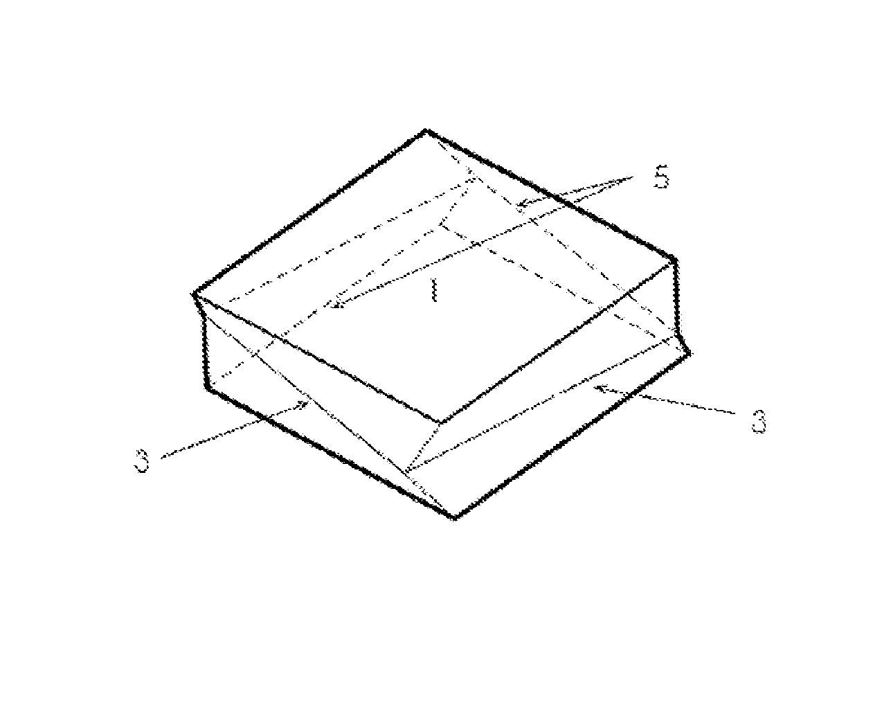
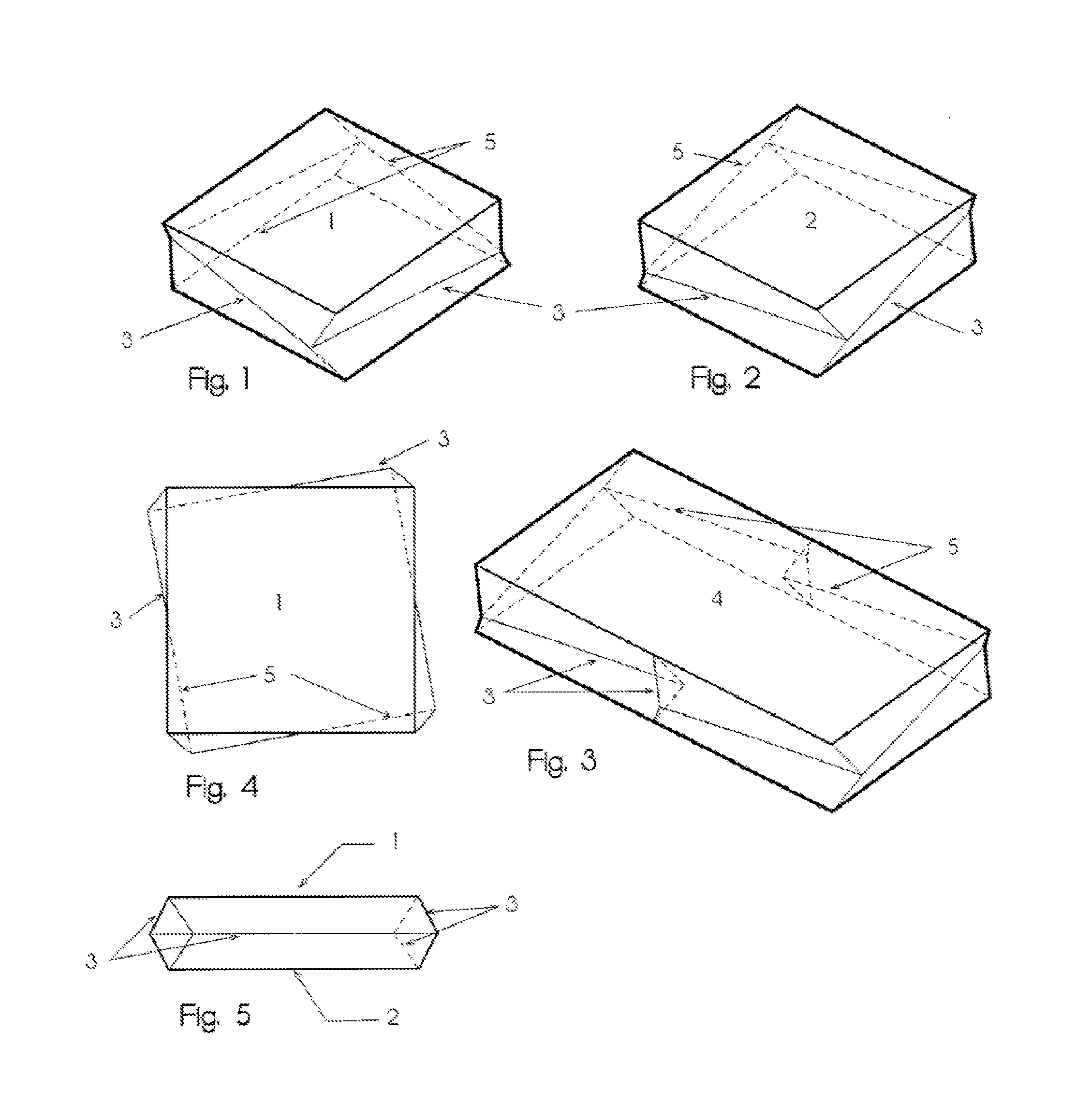
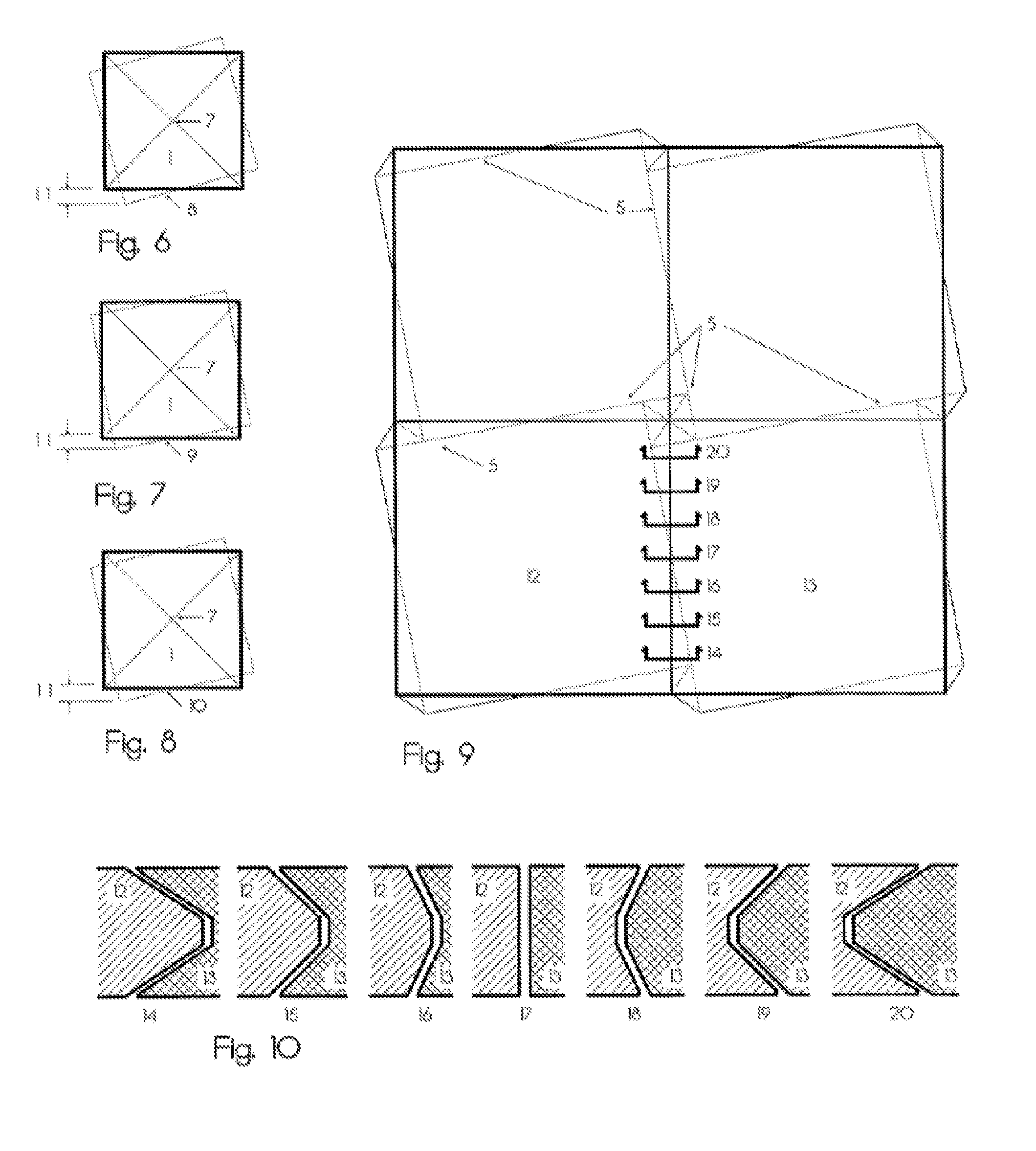
[0059]The devices and methods presented herein may be used in place of pavers and construction blocks, such as masonry blocks, of the prior art. In particular, a joint configuration is employed for pavers and wall block units that act as both a tongue and a groove in the same surface. All abutting surfaces of pavers are the preferably same and all abutting surfaces of masonry wall units are preferably the same. With oblong rectangular pavers and masonry units, the present joint configuration permits short sides to interlock with long sides when the units are laid on the block module with joints lining-up.

[0060]Preferably, the joint configuration forms what is referred to herein as a d...


PUM


Abstract

The disclosure provides, among other things, a paver that includes a body having a top surface, a bottom surface opposite the top surface, and a peripheral side. The peripheral side is defined about a perimeter of the paver and joins the bottom and top surfaces. The peripheral side defines a peripheral edge displaced from the top surface and the bottom surface that traverses the perimeter of the body along the peripheral side. The edge is adapted to engage a complementary edge on a peripheral side of an adjacent paver, such that the pavers interlock when a vertical force is applied to the paver. In another aspect, a masonry wall unit is provided for building walls similar in concept to the paver.

Description

BACKGROUND[0001]1. Field of the Disclosure[0002]In one aspect, the present disclosure is directed to interlocking precast or pre-molded pavers for enhanced smoothness of paved surfaces initially and over time. In another aspect, the disclosure describes an improved unit for the construction of walls, and preferably masonry walls.[0003]2. Description of Related Art[0004]Hard surfaced areas primarily outside of building interiors are more frequently paved with brick, stone and precast paving units set on gravel, sand and other porous surfaces than done previously, where concrete slabs and asphalt pavement was most frequently used. The desire for more visually pleasing surfaces and environmental laws limiting paved areas impervious to water penetration, has spurred use of individual pavers permitting rain to be absorbed into the ground through open joints between each paver, thereby reducing storm discharges to existing storm water carrying systems and resultant flooding.[0005]Individu...

Claims


Application Information

Patent Timeline
Patent Type & Authority Applications(United States)
IPC IPC(8): E01C5/00E04F13/14
CPCE01C5/00E04F13/14E01C5/06E01C2201/12
Inventor POLLACK, ROBERT
Owner HETTRICH HANSL
Why Eureka
Try Eureka