Axially-split radial turbine

Active Publication Date: 2013-10-24
HONEYWELL INT INC
View PDF6 Cites 12 Cited by
  • Summary
  • Abstract
  • Description
  • Claims
  • Application Information

AI Technical Summary

Problems solved by technology

However, as turbine inlet temperatures and rotational speeds increase, so too do the thermal and mechanical demands placed on the GTE components.
The turbine blades, in particular, are directly exposed to combustive gas flow at or near peak temperatures and are consequently heated to exceedingly high temperatures at which most alloys weaken or melt and become prone to oxidation or other forms of chemical degradation.
By comparison, the inner portion of the turbine (commonly referred to as the “turbine disk”) is largely shielded from direct exposure to combustive gas flow, but is subject to considerable mechanical stress resulting from the centrifugal forces acting on the turbine rotor at high rotational speeds.
However, due to the nature of their design, radial turbines are relatively lengthy in the axial direction.
As a result, a radial turbine can be undesirably heavy and cumbersome.
Axial turbines can readi

Method used


Image

  • Axially-split radial turbine
  • Axially-split radial turbine
  • Axially-split radial turbine

Examples


Embodiment Construction

[0016]The following Detailed Description is merely exemplary in nature and is not intended to limit the invention or the application and uses of the invention. Furthermore, there is no intention to be bound by any theory presented in the preceding Background or the following Detailed Description.

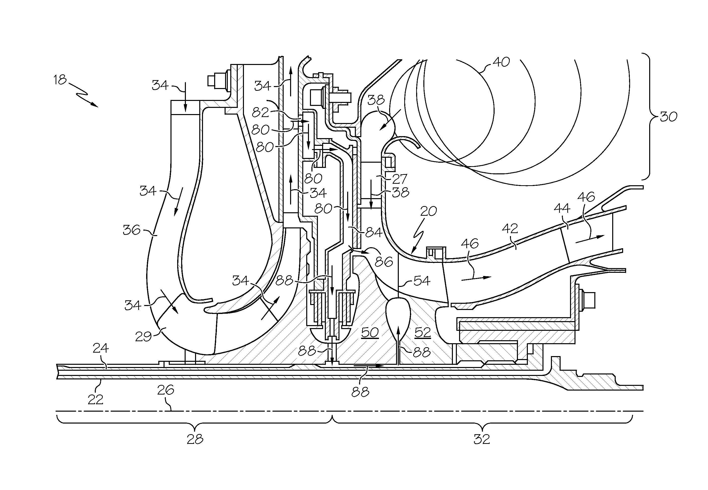
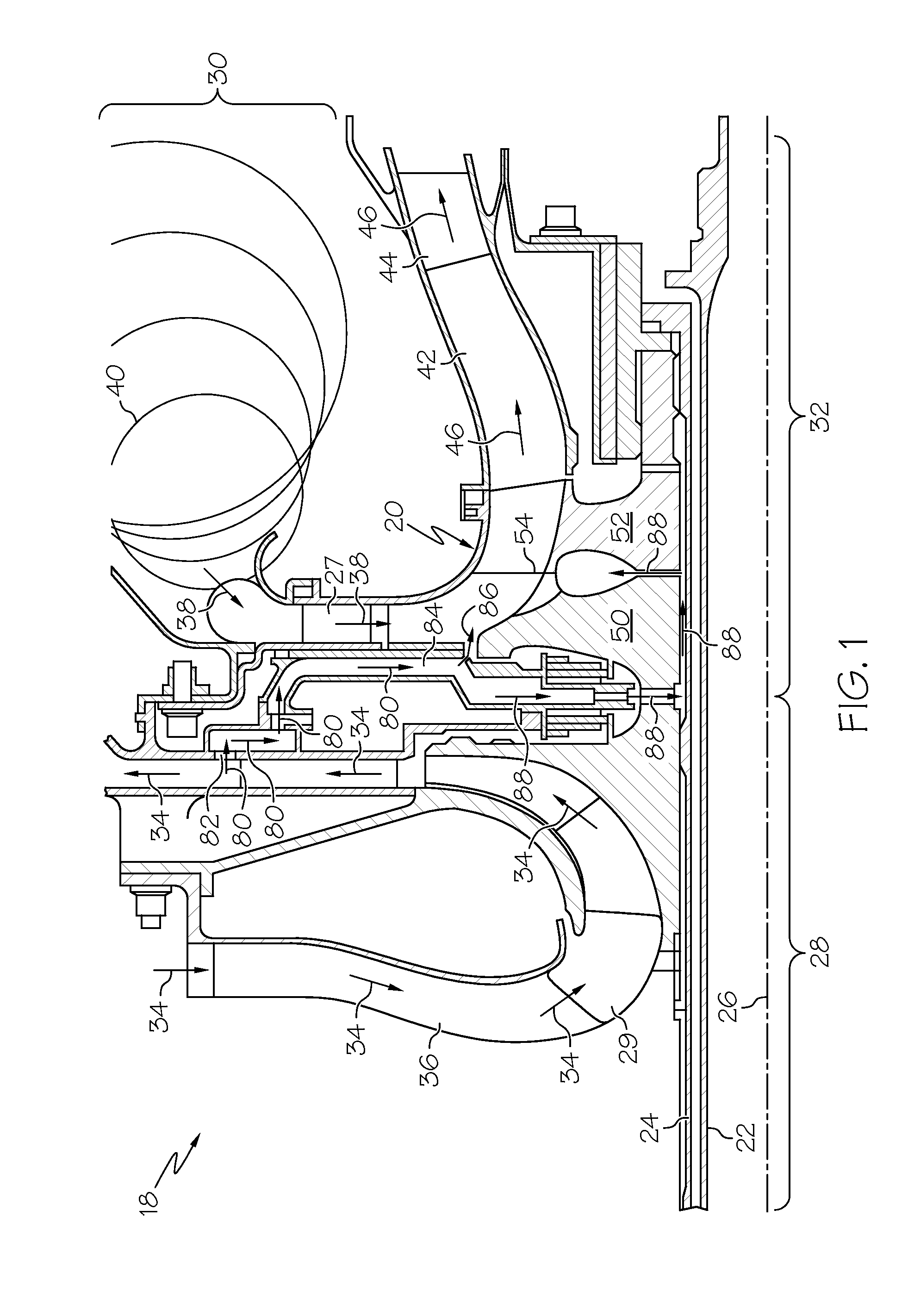
[0017]FIG. 1 is a simplified cross-sectional view of a portion of a gas turbine engine (GTE) 18 including an internally-cooled, axially-split radial turbine 20, as illustrated in accordance with an exemplary embodiment of the present invention. As illustrated in FIG. 1 and described herein, GTE 18 is offered by way of example only to provide a convenient and non-limiting context in which an exemplary embodiment of radial turbine 20 can be described. It will be readily appreciated that embodiments of axially-split radial turbine 20 can be employed within various types of gas turbine engines including, but not limited to, other types of turbofan, turboprop, turboshaft, and turbojet engines, wh...


PUM


Abstract

An axially-split radial turbine includes a forward rotor section and an aft rotor section being mechanically and abuttingly coupled to one another along an annular interface that resides within a plane generally orthogonal to a rotational axis of the axially-split radial turbine. The axially-split radial turbine can be provided as part of a gas turbine engine.

Description

TECHNICAL FIELD[0001]The present invention relates generally to gas turbine engines and, more particularly, to axially-split radial turbines for usage within gas turbine engines.BACKGROUND[0002]Gas turbine engines (“GTE”) have been engineered extensively to improve efficiency, thrust-to-weight ratios, and other measures of engine performance. One of the most direct manners by which engine performance can be improved is through increases in the core rotational speeds and turbine inlet temperatures generated during engine operation. However, as turbine inlet temperatures and rotational speeds increase, so too do the thermal and mechanical demands placed on the GTE components. The most demanding performance requirements are typically placed on the high pressure turbine rotor or rotors, which are positioned immediately downstream of the GTE combustion section and which rotate at the greatest speed during engine operation. The turbine blades, in particular, are directly exposed to combus...

Claims


Application Information

Patent Timeline
IPC IPC(8): F01D13/00
CPCF01D5/04F01D5/066F01D5/085F04D29/28F05D2230/23Y02T50/60F01D5/026F01D5/088F01D5/18F01D1/24
Inventor JAN, DAVID K.ZOLLARS, CHRISTOPHERRANA, RAJIVPOLAKIS, TOMRIAHI, ARDESHIR
Owner HONEYWELL INT INC
Why Eureka
Try Eureka