Glass film cutting method and glass film laminate

Inactive Publication Date: 2013-10-24
NIPPON ELECTRIC GLASS CO LTD
View PDF0 Cites 73 Cited by
  • Summary
  • Abstract
  • Description
  • Claims
  • Application Information

AI Technical Summary

Benefits of technology

The present invention relates to a method for making a glass film that can be easily attached to a support glass. By using a laser to heat and cool the glass film, a sufficient amount of thermal stress is created in the film, allowing for the formation of precise lines. This technique provides a reliable and efficient way to make glass films with high precision.

Problems solved by technology
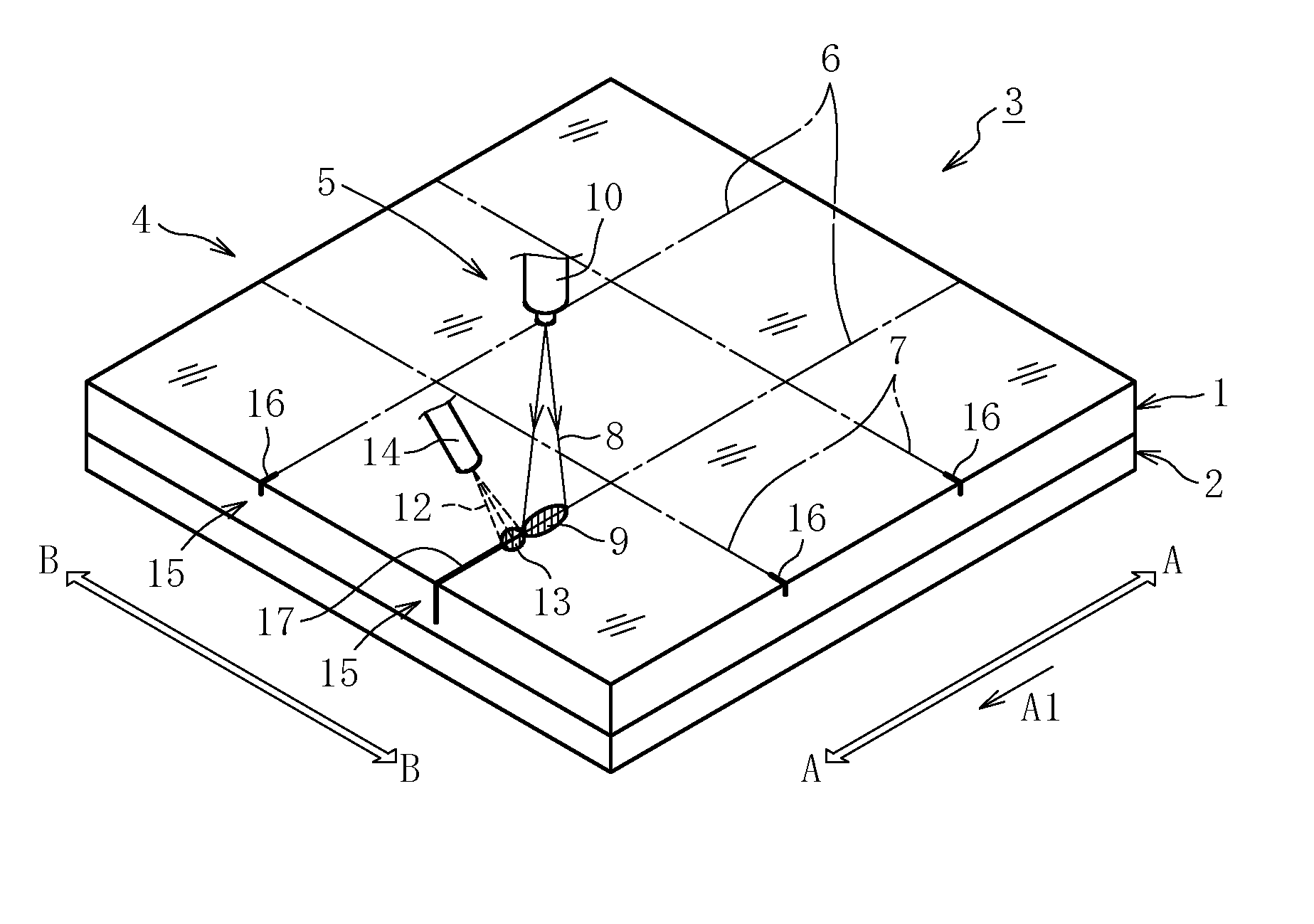
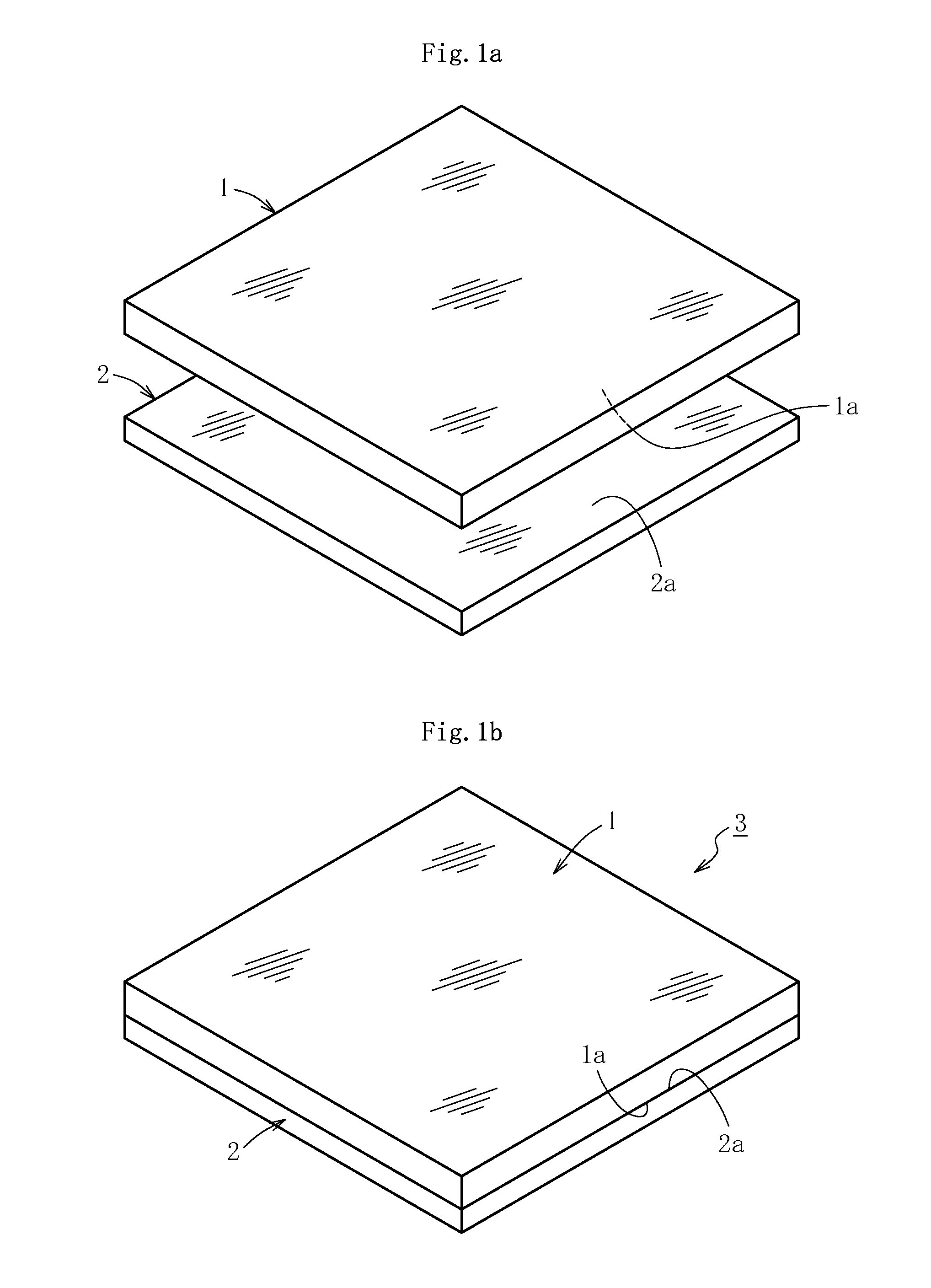
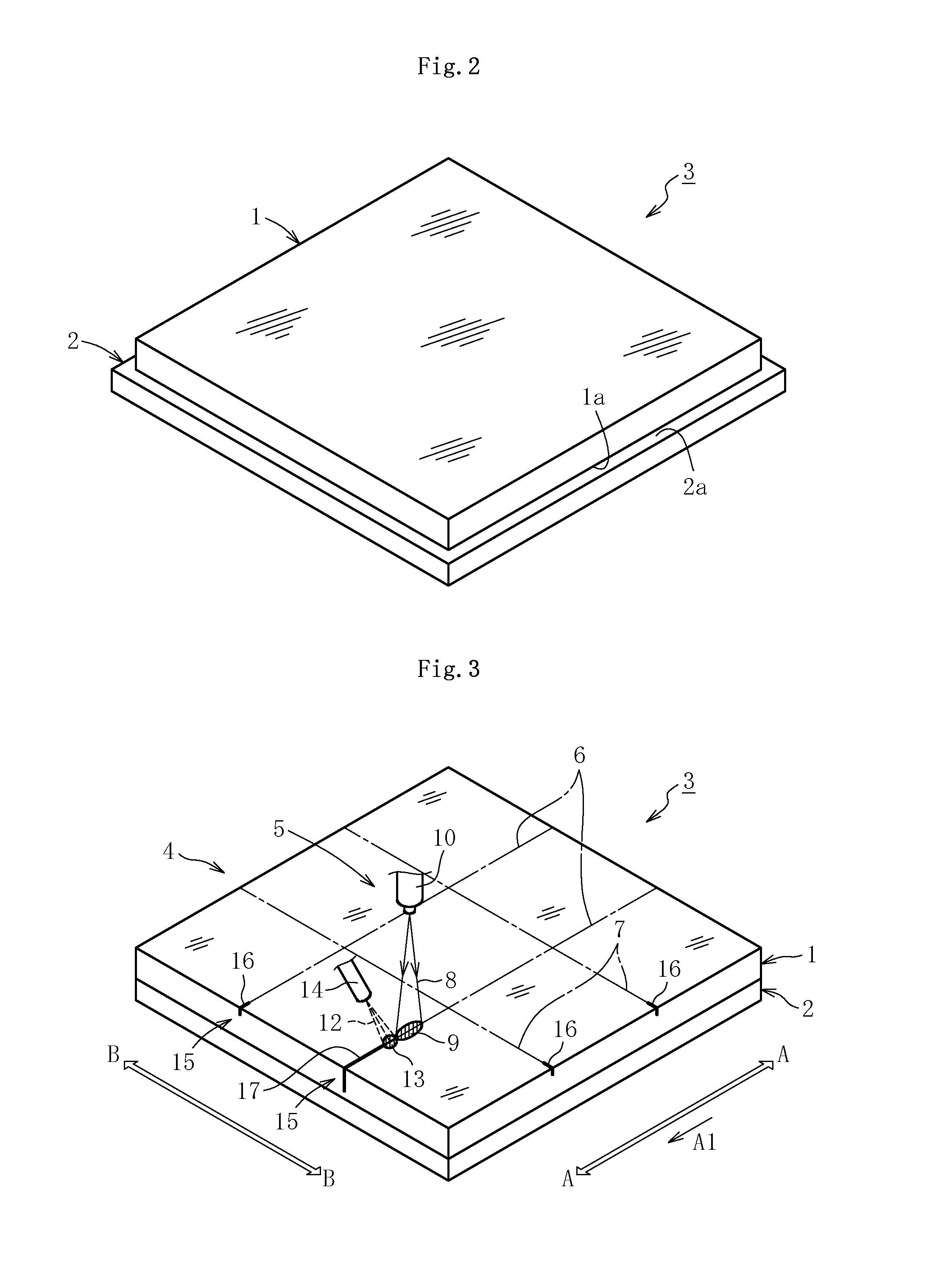
The technical problem addressed in this patent text is the need for a method to cut and separate thin glass films (less than 200 μm) used in electronic devices such as displays and illumination devices, as they require high flexibility. The current methods of laser scribing involve heating and cooling the glass sheet to form scribe lines, which are then used to separate the glass film into smaller pieces. However, there is a need for a more precise and efficient method to achieve this.

Method used


Image

  • Glass film cutting method and glass film laminate
  • Glass film cutting method and glass film laminate
  • Glass film cutting method and glass film laminate

Examples


examples

[0062]As shown in Table 1 below, Examples 1 to 5 of the present invention are each directed to a case where the laminate is manufactured by adhering the glass film, in which the scribe lines are to be formed, and the support glass to each other through the surface contact therebetween, and the surface roughnesses Ra of the contact surfaces of the glass film and the support glass are set to 2.0 nm or less. On the other hand, Comparative Examples 1 and 2 are each directed to a case where the laminate is manufactured from the glass film and the support glass in a manner similar to the above, but one of the surface roughnesses Ra of the contact surfaces of the glass film and the support glass is more than 2.0 nm. Further, Comparative Examples 3 and 4 are each directed to a case where the support glass is not provided.

[0063]In each of Examples 1 to 5 and Comparative Examples 1 to 4, through use of alkali-free glass (OA-10G) manufactured by Nippon Electric Glass Co., Ltd., the sizes of th...


PUM

PropertyMeasurementUnit
Lengthaaaaaaaaaa
Thicknessaaaaaaaaaa
Thicknessaaaaaaaaaa

Abstract

A glass film laminate is manufactured by setting a surface roughness Ra of a surface of a glass film having a thickness of 200 μm or less to contact a support glass, which supports the glass film, and a surface of the support glass to contact the glass film to 2.0 nm or less, and by bringing the surfaces of the glass film and the support glass into surface contact with each other. After that, a laser scribing operation is carried out, in which a scribe line is formed in the glass film by propagating an initial crack through laser heating of the glass film followed by subsequent cooling of the glass film.

Description


Claims


Application Information

Patent Timeline
Owner NIPPON ELECTRIC GLASS CO LTD
Why Eureka
Try Eureka