Energy generation system including pontoon unit and water wheel

a technology of energy generation system and water wheel, which is applied in the direction of sea energy generation, pontoons, floating buildings, etc., can solve the problems of not being able to move the water wheel system easily, the water wheel is not optimized for and the frame is not designed to give a high energy output. , to achieve the effect of optimizing the shape of the venturi for generating energy

Inactive Publication Date: 2013-10-31
BELARBI MOHAMED SAHBI
View PDF3 Cites 18 Cited by
  • Summary
  • Abstract
  • Description
  • Claims
  • Application Information

AI Technical Summary

Problems solved by technology

The first thing is the framework, which is not designed to be able to give a high energy output.
Furthermore, the water wheel is not optimized for a high energy output.
One problem with using this type of traditional water wheel system is that the wheel, and its surrounding structure, is firmly and more or less immovably arranged at one location.
It is not an easy task to move the water wheel system, i.e. the water wheel and its surrounding structures, without much difficulty and labour.
One problem with this solution is that it is quite large and bulky, hence taking up much space in a water stream, e.g. a river, and during transportation.
Also, this solution does not optimise the power output as compared to its size.
Is should be noted that one important issue with using this type of horizontal water wheels is that actually only 50% of the water power is used due to the water wheel being constantly submerged.

Method used


Image

  • Energy generation system including pontoon unit and water wheel
  • Energy generation system including pontoon unit and water wheel
  • Energy generation system including pontoon unit and water wheel

Examples


Embodiment Construction

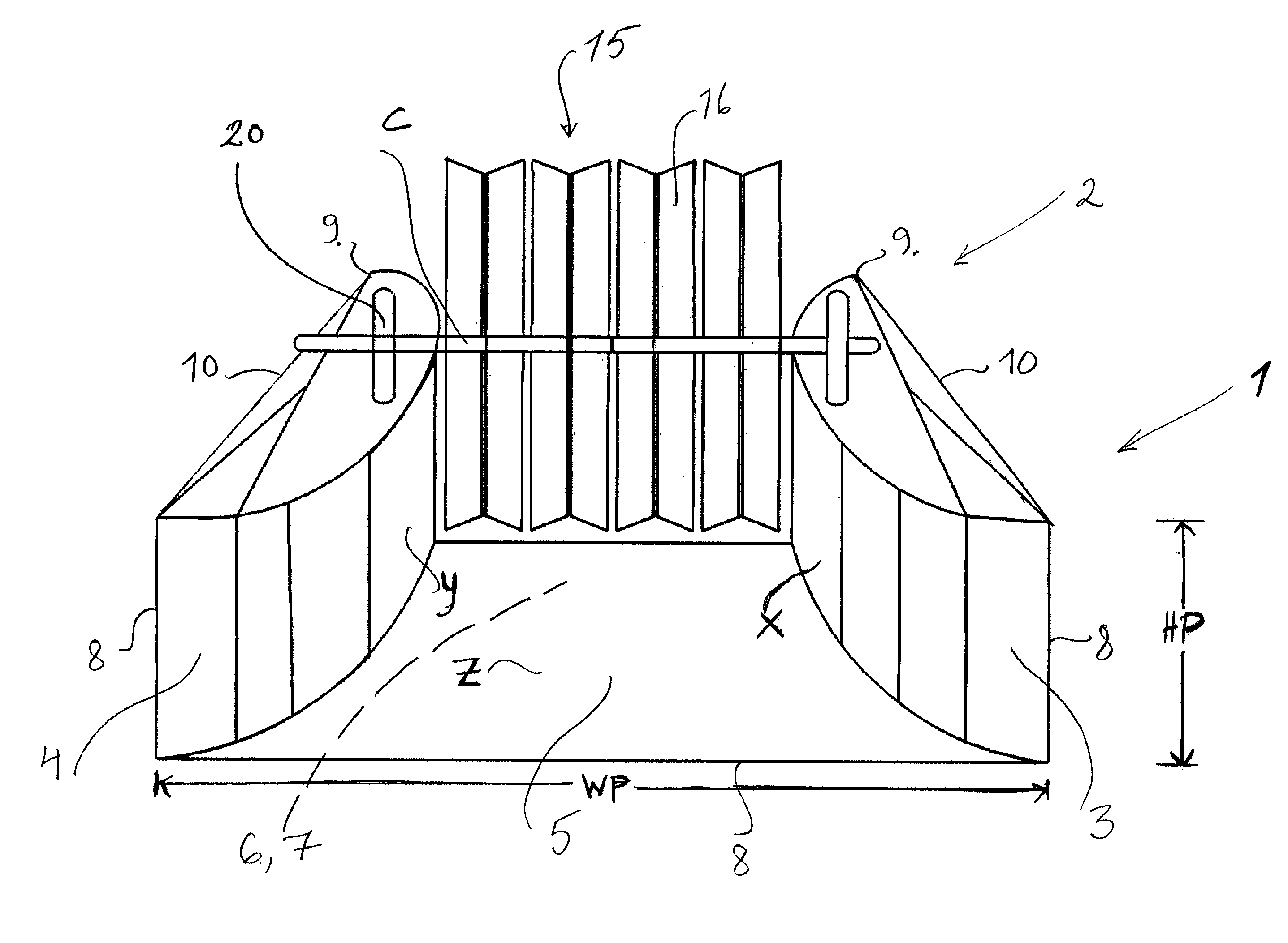
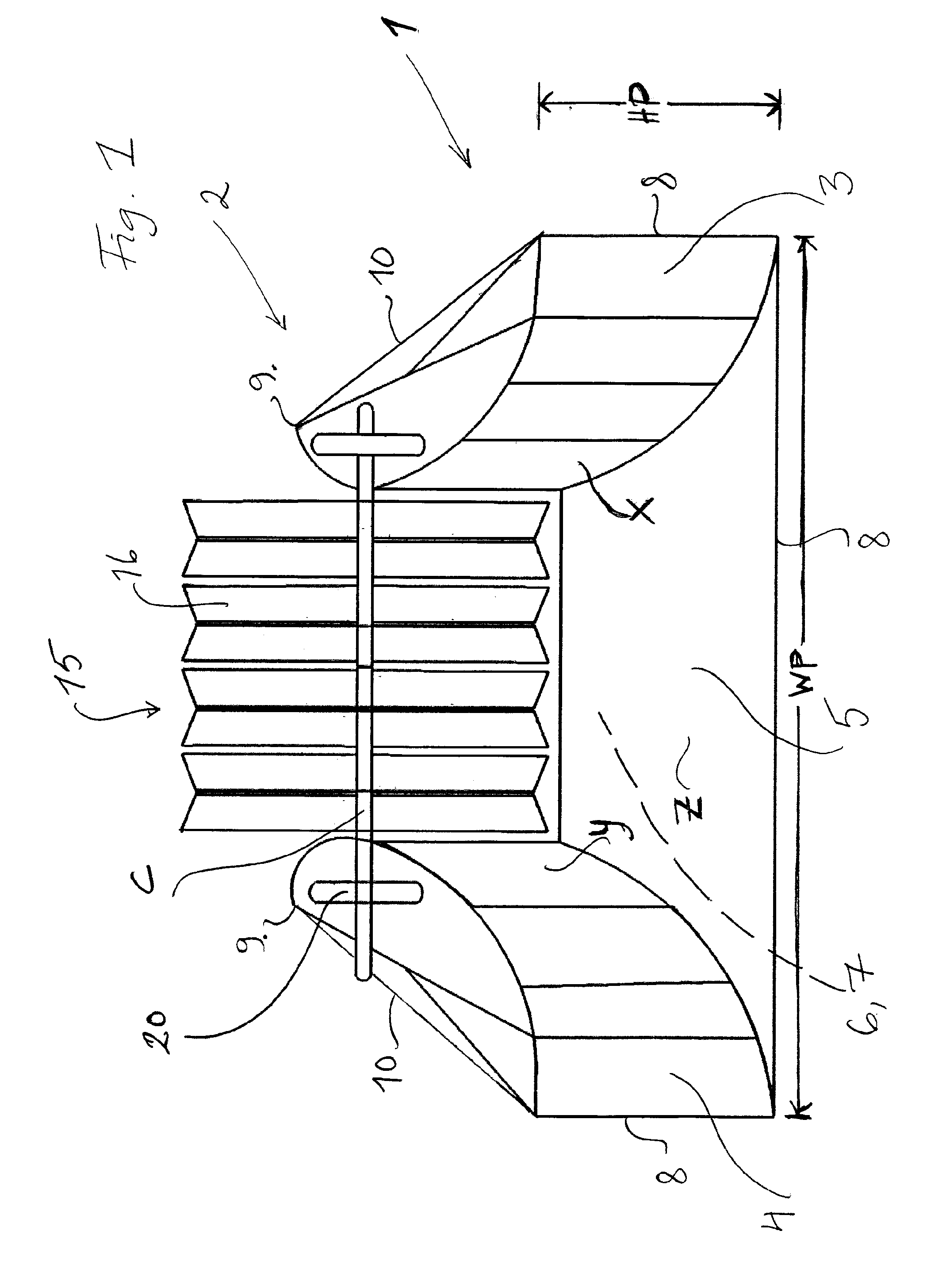
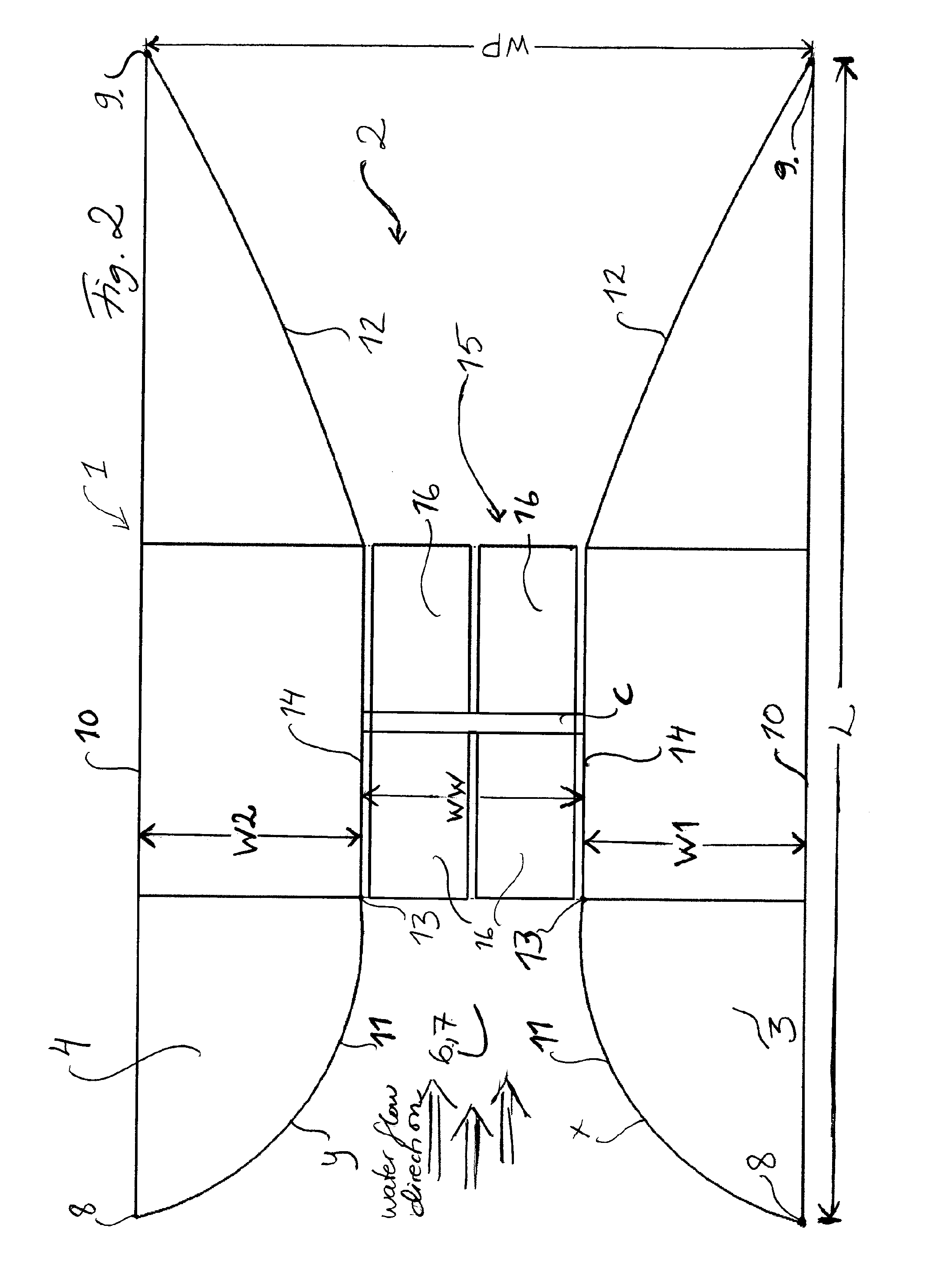
[0022]According to one embodiment of the present invention, the first water surface pontoon part 3 and the second water surface pontoon part 4 have substantially the same geometrical shape and are mirror-inverted arranged to each other. This may be seen in FIG. 1 and FIG. 2. According to another embodiment, each pontoon part is pointed at the front end and at the rare end. This is of importance to keep the water flowing resistance as low as possible. Furthermore, according to one specific embodiment, each pontoon part has a substantially straight long side, said long side being the side facing away from the inner of the pontoon unit. In FIGS. 1 and 2 such water surface pontoon parts having both pointed ends and straight long sides may be seen, however the same shape is preferred also for the bottom pontoon part. The straight longs sides are of interest for having as short water distance on the non-water wheel side as possible. This gives rise to as large difference as possible betwe...


PUM


Abstract

The present invention relates to a pontoon unit 1 intended for an energy generation system 2, said pontoon unit 1 comprising one first water surface pontoon part 3 having an unsymmetrical convexly curved inner surface X, a second water surface pontoon part 4 having an unsymmetrical convexly curved inner surface Y, and one bottom pontoon part 5 being substantially perpendicular to the first and second water surface pontoon parts 3, 4 and also having an unsymmetrical convexly curved inner surface Z.

Description

FIELD OF INVENTION[0001]The present invention relates to a pontoon unit and a water wheel intended for an energy generation system, and also such an energy generation system.TECHNICAL BACKGROUND[0002]Energy generation systems comprising some kind of pontoon or framework and water wheels exist today.[0003]For example, US20070222219 discloses a hydroelectric device including generally a base portion with a top surface, a bottom surface, and opposing sidewalls defining an interior space of the base portion. The interior space of the base portion is such that it is wider near the ends of the base portion and narrower in the interior of the base portion, essentially forming a venturi. The base portion also includes a central slot along a longitudinal axis thereof. Furthermore, US20070222219 also discloses a wheel support portion fixedly attached to the base portion, a wheel portion rotatably attached to the wheel support portion and having a plurality of blades extending from a center th...

Claims


Application Information

Patent Timeline
Patent Type & Authority Applications(United States)
IPC IPC(8): F03B13/10B63B35/34
CPCF03B13/10B63B35/34F03B17/063F05B2240/932Y02E10/20Y02E10/30
Inventor BELARBI, MOHAMED SAHBI
Owner BELARBI MOHAMED SAHBI
Why Eureka
Try Eureka