Hydraulically automatic lifting flood prevention walls and automatic lifting method

A hydraulic automatic, flood control wall technology, applied in the direction of breakwaters, water conservancy projects, engine components, etc., can solve the problem of reducing the value and charm of waterfront buildings, making it difficult for high-value waterfront spaces, and not really releasing the landscape value of the urban hinterland development zone on the water surface of the river And other issues

Pending Publication Date: 2016-11-16
NORTH CHINA UNIV OF WATER RESOURCES & ELECTRIC POWER
View PDF0 Cites 21 Cited by
  • Summary
  • Abstract
  • Description
  • Claims
  • Application Information

AI Technical Summary

Problems solved by technology

However, the application of these new technologies and concepts has not fundamentally changed the barrier characteristics of the dam; nor has it truly released the landscape value of the river water surface in its urban hinterland development zone
Generally speaking, the elevation of the top of the embankment will be at least 4 meters higher than that of the development plot, and the first or even second floors of the buildings adjacent to the river bank cannot see the water surface at all, but "nest" in the shadow of the river bottom; at the same time, The bottom two floors of the building are probably used for commercial development, which greatly reduces the value and charm of waterfront buildings
Moreover, it is not easy to form a high-energy, high-value waterfront space to accommodate public activities

Method used


Image

  • Hydraulically automatic lifting flood prevention walls and automatic lifting method
  • Hydraulically automatic lifting flood prevention walls and automatic lifting method
  • Hydraulically automatic lifting flood prevention walls and automatic lifting method

Examples


Embodiment 1

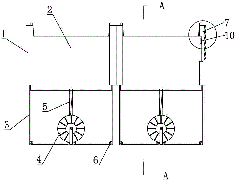
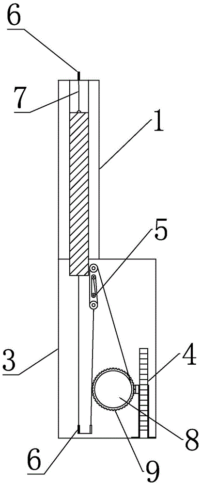
[0028] Embodiment 1 A hydraulic automatic lifting flood wall, see Figure 1-5 : Arranged side by side along the inner side of the embankment, including a driving device, a locking mechanism 10, a column 1, a base 3, and a baffle 2, the base 3 is a hollow cavity, and the inner cavity of the base 3 is slidably equipped with a baffle 2 through the vertical column 1, The side of the column 1 is provided with a chute corresponding to the baffle plate 2;

[0029] The inner cavity of the base 3 is provided with a driving device corresponding to the baffle plate 2, and the driving device includes a water wheel 4 and a pulley block, and the water wheel 4 drives the baffle plate 2 to move up and down along the chute through the pulley block;

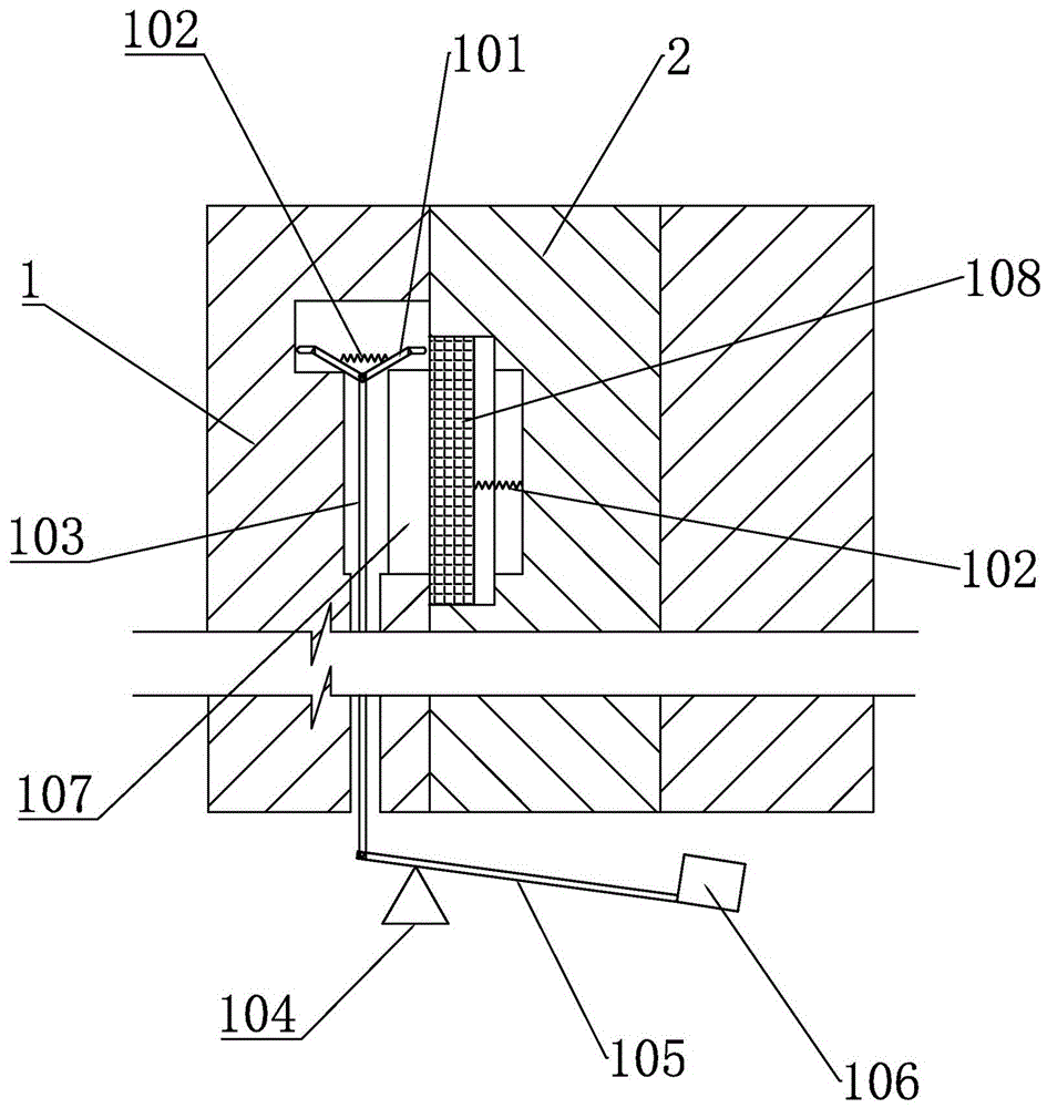
[0030] A locking mechanism 10 is provided on the inner wall of the corresponding chute on both sides of the baffle plate 2. The locking mechanism 10 includes a floating block 106, a pull rod 103, a driving rod, and a block. Two articulated rods 1...

Embodiment 2

[0037] Embodiment 2 A kind of automatic lifting method of hydraulic automatic lifting flood control wall, see Figure 1-5 : Including the following steps:

[0038] (1) A number of hydraulic automatic lifting flood walls are arranged side by side on the inner wall of the embankment, and the baffle 2 is accommodated in the inner cavity of the base 3;

[0039] (2) As the water level rises, the flood flows into the inner cavity of the base 3, and the water wheel 4 is driven by the water flow. The water wheel 4 generates upward traction on the baffle 2 with the help of the movable pulley block 5 and the direction-changing pulley, and the baffle 2 rises slowly with the rotation of the water wheel 4. ;

[0040] (3) As the water level rises, the water level in the base 3 gradually increases, the floating block 106 pulls the pull rod 103 downward through the fulcrum 104, and the two hinged rods 101 on the top of the pull rod 103 press the block outward through the spring 102, and the ba...


PUM


Abstract

The invention relates to a hydraulic automatic lifting flood control wall, which is arranged side by side along the inner side of a river embankment, and includes a driving device, a locking mechanism, a column, a base, and a baffle. The side of the column is provided with a chute corresponding to the baffle; the inner cavity of the base is provided with a driving device corresponding to the baffle, and the driving device includes a water wheel and a pulley block, and the water wheel drives the baffle to move up and down along the chute through the pulley block ;A liftable baffle is set up. The baffle is hidden in the base of the flood control wall during non-flood season. When the flood arrives and reaches a certain water level, the flood control baffle will automatically rise under the action of the traction force of the waterwheel. After the baffle rises to the upper part of the column, The bayonet on the top of the baffle is docked with the locking mechanism on the column to form a fixed connection relationship, and the baffle is used to block the flood and complete the flood control task.

Description

technical field [0001] The invention belongs to the field of urban flood control, and in particular relates to an automatic lifting flood control wall that takes into account both urban flood control and urban landscape. Background technique [0002] At present, river embankments in cities are effective channels to avoid flood disasters, and can release floods in summer, effectively protecting the safety of cities in the river basin. In order to control the destructive effect of the peak water flow of the river on the hinterland of the river channel, parallel flood embankments or flood walls are often built along both sides of the river channel to avoid possible damage caused by floods, such as floods that will cause changes in the ecological environment in the watershed, It causes changes in the river course, soil erosion and barren land, etc., and even washes away and destroys the vegetation and buildings on the river bank, which poses a huge threat to people. Therefore, ...

Claims


Application Information

Patent Timeline
Patent Type & Authority Applications(China)
IPC IPC(8): E02B3/06F03B13/00
CPCE02B3/06E02B3/066F03B13/00
Inventor 韩立炜马春雨秦宇卓帅宇邢晓欢张宏洋郭磊徐存东
Owner NORTH CHINA UNIV OF WATER RESOURCES & ELECTRIC POWER
Why Eureka
Try Eureka