System and method for variable speed generation of controlled high-voltage DC power

a high-voltage dc power and variable speed technology, which is applied in the control system, control of electrical equipment, and control of electric generators, can solve the problems of reliability problems, voltages achieved within generators, and voltage variations, so as to simplify the overall system electronics and simplify the weight and complexity of transformers

a high-voltage dc power and variable speed technology, which is applied in the control system, control of electrical equipment, and control of electric generators, can solve the problems of reliability problems, voltages achieved within generators, and voltage variations, so as to simplify the overall system electronics and simplify the weight and complexity of transformers

US20130181688A1Inactive Publication Date: 2013-07-18RAVEN ENERGY ALTERNATIVES

Image

  • System and method for variable speed generation of controlled high-voltage DC power
  • System and method for variable speed generation of controlled high-voltage DC power
  • System and method for variable speed generation of controlled high-voltage DC power

Examples


Embodiment Construction

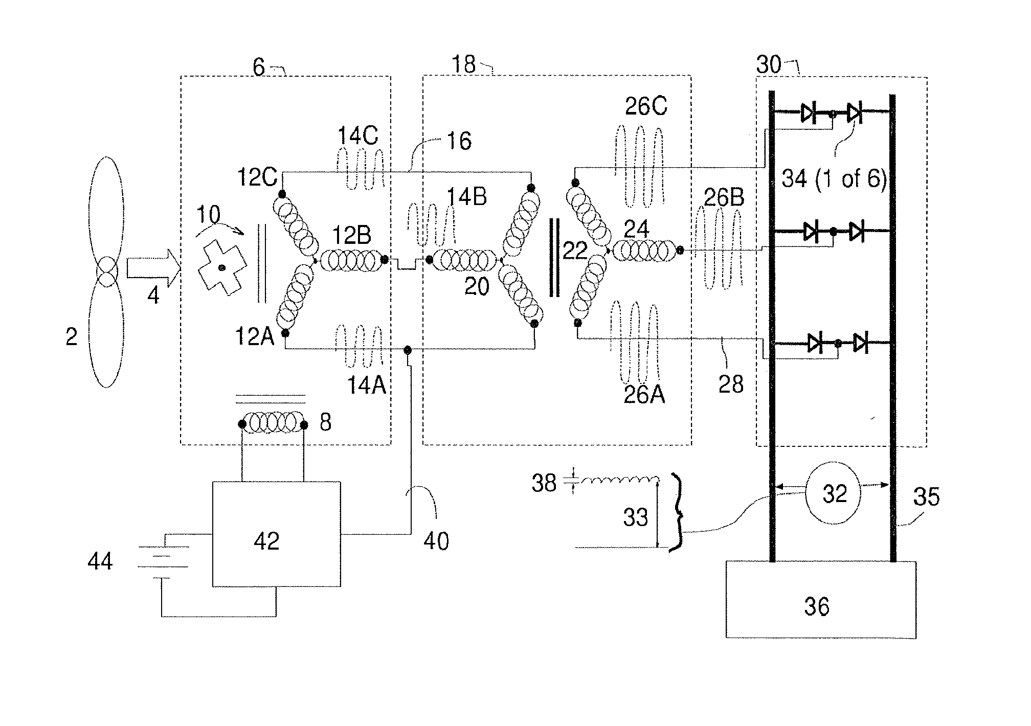
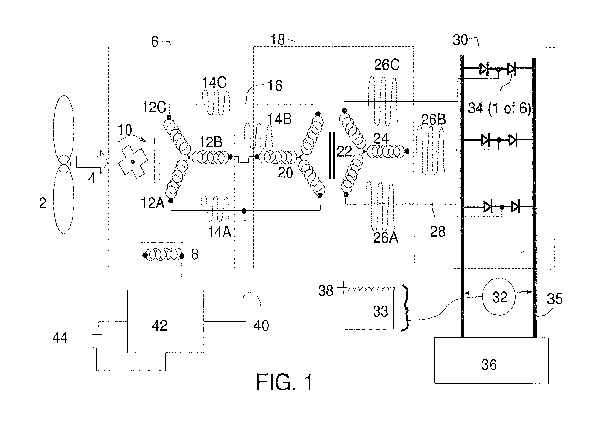
[0015]Referring to FIG. 1, a system and method for variable speed generation of controlled high-voltage DC power may be understood by examining the schematic arrangement of flow of mechanical and electrical power and signals for the preferred embodiment. A source of variable speed mechanical power 2, which may be a wind turbine, water wheel, steam turbine, or gas turbine or other such device, provides power to turn, at variable speeds, a shaft 4 connected to a high-frequency alternator 6, which includes one or more field coil(s) 8, which can be energized by field coil electrical currents to produce magnetic fields magnetically coupled to magnetic structure 10 that moves with the shaft rotation. This motion of magnetic structure 10 causes variation of the magnetic intensity within multiple phases of magnetically coupled output windings, typically three stationary armature windings as shown here by 12A, 12B, 12C, which are magnetically coupled to magnetic structure 10; this variation ...


PUM


Abstract

A system and method are disclosed for advantageously using field-controlled high-frequency alternators for the generation of controlled high-voltage DC power from variable speed mechanical power sources such as wind turbines, water wheels, and gas or steam turbines. The production of controlled high-voltage DC power without involving hard switching of the full output power is described.

Description

BACKGROUND OF THE INVENTION[0001]1. Field of Invention[0002]The invention relates generally to the use of field-controlled high-frequency alternators for generating electrical power, and more specifically to generating controlled output power from the variable speed operation of a mechanical power source such as a wind turbine or similar power source, and its interconnection with high voltage DC distribution lines.[0003]2. Description of the Prior Art[0004]There is a need for improved methods of generating electricity from variable speed sources such as wind power, hydro power, and from waste heat recovery systems employing steam cycle machines or gas turbines or similar equipment. Taking wind power as an example, there are various methods for converting wind power to electrical power. There are systems that utilize power generators which operate directly in synchrony with the grid power frequency, such systems including synchronous generators, which require constant speed shafts, a...

Claims


Application Information

Patent Timeline
18 Jul 2013
Publication
US20130181688A1
IPC
H02P9/36
CPC
H02P9/02; H02P9/36; H02P9/48
Inventors
TUPPER, CHRISTOPHER N.; WOOD, DUNCAN G.