Load driving device and system, limiting point control method and device

a technology of load driving device and load unit, which is applied in the field of circuits, can solve the problems of increasing the complexity of the circuit, affecting the reliability of the driver, and serious heat of the driver, so as to improve the reliability reduce the heat source of the driving device, and increase the set distance between the driving device and the load unit.

Active Publication Date: 2013-10-31
INVENTRONICS HANGZHOU
View PDF8 Cites 2 Cited by
  • Summary
  • Abstract
  • Description
  • Claims
  • Application Information

AI Technical Summary

Benefits of technology

[0050]An analysis of the technical effect of the above solutions is as follows.
[0051]In the load driving device and system, the input terminal of the sampling unit is connected to the output terminal of the voltage and current regulative main circuit, so as to sample the output voltage. In this way, the current-limiting circuit and the driving device in the load branch may be packaged separately, and the set distance between the driving device and the load unit may be increased, and thus the heat source of the driving device is reduced and the reliability of the driving device is improved.
[0052]Moreover, the electric energy transmission between the electric energy supplying unit and the load unit may be achieved by two connection wires, the wiring is simple, and thus the complexity of the circuit is reduced. Further, when the amount of the load branches is varied, for example, when a load branch is cut off or another branch is added, the voltage and current regulative main circuit may automatically adjust the output voltage via the sampling unit and the control of the output current controller, the constant-current driving of the other load branches is achieved. In this way, no open protection circuit needs to be provided for each load branch separately, thus the complexity of the circuit is further reduced and the cost is saved.

Problems solved by technology

Firstly, in order to facilitate the minimum value sampling circuit of the driver to perform a voltage sampling on the post stage circuit, the linear adjustment current-limiting circuit 203 of each LED branch often needs to be enclosed inside the driver, the loss of the adjustment transistor is large when the voltage difference between the multiple of LED branches is large, resulting in serious heat of the driver. Moreover, the driver is generally placed nearby the LED light source inside the LED lighting device, thus the temperature thereof will be higher, which affects the reliability of the driver seriously.
Secondly, the output voltage control circuit 204 of the previous output voltage adjustable voltage source 201 needs to sample the voltage of the post stage circuit composed of a LED and the corresponding linear adjustment current-limiting circuit 203, so that the wiring between the previous output voltage adjustable voltage source 201 and the post stage circuit is complicated. Moreover, when an open circuit fault occurs in a certain LED load, the drain voltage of the linear adjustment transistor is zero. Therefore, it is necessary to further provide an open circuit protection for each LED load, so as to ensure that other LED loads in which no fault occurs can operate normally in this case, which further increases the complexity of the circuit.

Method used


Image

  • Load driving device and system, limiting point control method and device
  • Load driving device and system, limiting point control method and device
  • Load driving device and system, limiting point control method and device

Examples


Embodiment Construction

[0062]Specific implementations of a load driving device and a load driving system according to an embodiment of the invention will be described in detail in conjunction with the drawings hereinafter.

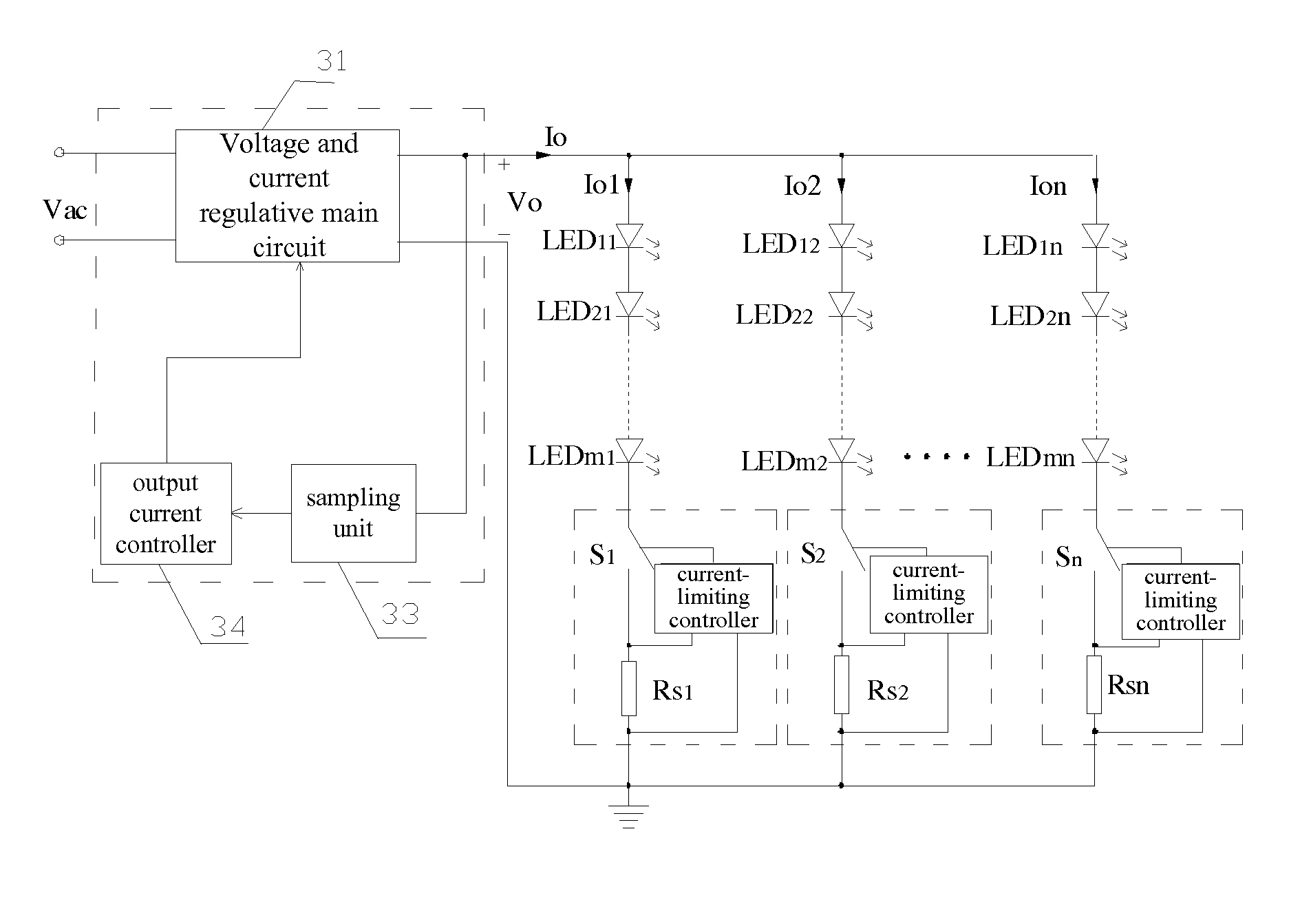
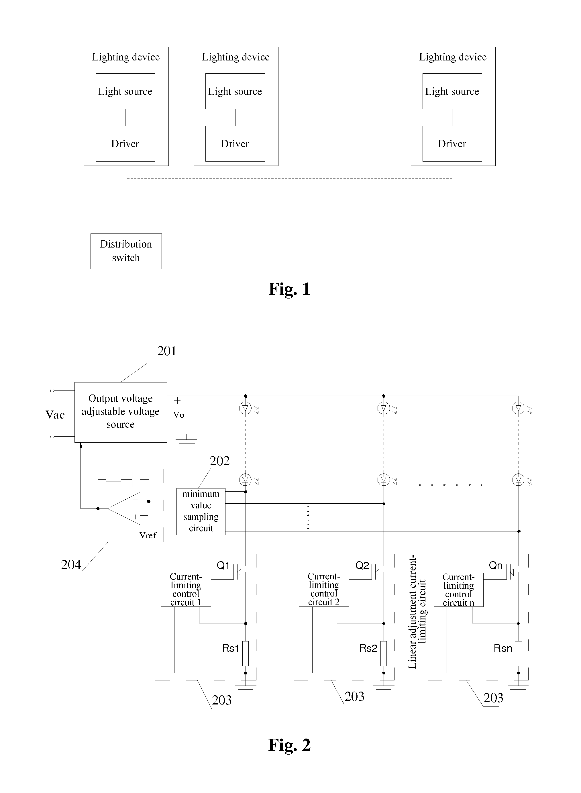
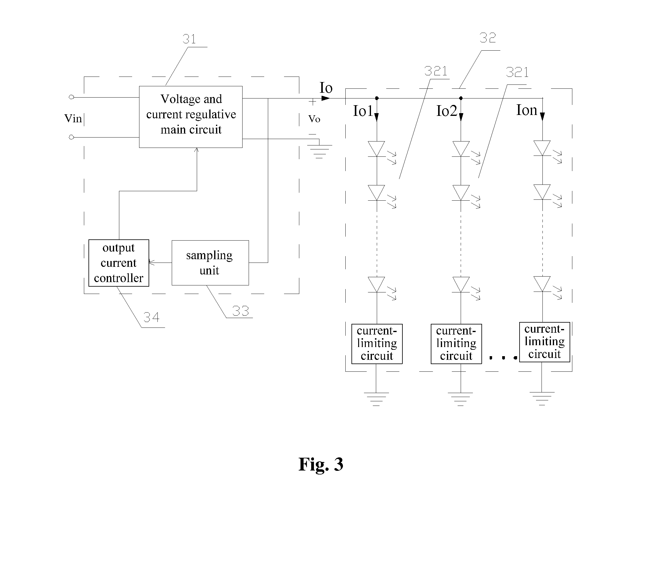
[0063]A load driving device according to an embodiment of the invention includes the following components:

[0064]a voltage and current regulative main circuit adapted to perform a voltage conversion on an input voltage under the control of an output current controller, and supply electric power to a load unit in a post stage;

[0065]a sampling unit connected to an output terminal or two output terminals of the voltage and current regulative main circuit, and adapted to sample an output characteristic parameter of the voltage and current regulative main circuit and transmit to an output current controller the sampled signal obtained by the sampling; and

[0066]the output current controller having an input terminal connected to an output terminal of the sampling unit, and adapted to control a c...


PUM


Abstract

A load driving device and system, and a limiting point control method and device. The load driving device comprising: a voltage/current regulative main circuit placed under the control of an output current controller, for use in conducting a voltage conversion on an input voltage, and in supplying electric power to a subsequent load unit; a sampling unit connected to an output terminal of the main circuit, for use in sampling an output feature parameter of the main circuit; the output current controller, for use in controlling a limiting point of the main circuit, and on the basis of the adjustment direction of the limiting point and on changes of the output feature parameters of the main circuit before and after an adjustment, determining a steady working point for the main circuit, and controlling the main circuit to work at the steady working point. The load driving device and system enable an increase in driver reliability and a reduction in circuit complexity.

Description

[0001]This application claims the priority of Chinese Patent Application No. 201010616067.X, entitled “LOAD DRIVING DEVICE AND SYSTEM, CURRENT LIMIT CONTROL METHOD AND DEVICE”, filed with the Chinese State Intellectual Property Office on Dec. 30, 2010, which is incorporated by reference in its entirety herein.FIELD OF THE INVENTION[0002]The invention relates to the field of circuit, and in particular to a load driving device and a load driving system.BACKGROUND OF THE INVENTION[0003]Most of the existing Light Emitting Diode (LED) luminaries have the structures which is designed based on the conventional gas discharge lamp and Tungsten lamp. The driving scheme which follows the conventional idea includes: providing one driver for one light source, and using a conventional AC / DC conversion technique with single-path or multi-path output. As shown in FIG. 1, a lighting device includes a light source and a driver, and is controlled by a distribution switch. As shown in FIG. 1, the drive...

Claims


Application Information

Patent Timeline
Patent Type & Authority Applications(United States)
IPC IPC(8): H05B33/08H05B44/00
CPCH05B33/0815H05B45/46Y02B20/30H05B45/3725
Inventor GE, LIANG'ANHUA, GUICHAOYAO, XIAOLILIU, YANG
Owner INVENTRONICS HANGZHOU
Why Eureka
Try Eureka