Eureka AIR delivers breakthrough ideas for toughest innovation challenges, trusted by R&D personnel around the world.

System and method for printing on a flexible body

a flexible body and printing system technology, applied in printing presses, typewriters, printing, etc., can solve the problems of difficult printing of information on the surface of flexible objects, additional difficulties in printing on flexible objects, and inability to print information on flexible objects

Active Publication Date: 2013-10-31
ILLINOIS TOOL WORKS INC
View PDF10 Cites 12 Cited by
  • Summary
  • Abstract
  • Description
  • Claims
  • Application Information

AI Technical Summary

Benefits of technology

The patent text describes a method for securing a flexible body in a printing system using a bed and a fixation device. The method prevents the flexible body from being removed when pulled in a direction that may flatten the printing surface. The technical effect of this patent text is improved flexibility and stability in the printing process.

Problems solved by technology

Some objects, however, can be difficult to print the information on surfaces of the objects.
For example, flexible (e.g., non-rigid) objects can be difficult to print on due to the flexible nature of the objects and the tendency for the objects to shift, move, and the like, during the printing process.
Some flexible objects present additional difficulties involved with printing on the objects.
For example, three dimensional flexible objects can be difficult to print on if there is not a relatively flat surface on which to print.
Rounded enclosures, such as intravenous (IV) bags that are filled with a fluid can be difficult to print on.
Due to the need to sanitize the IV bags after the printing process, however, the inks used to print on the IV bags may be exposed to harsh environments, such as caustic materials, heat, and the like.
As a result, relatively expensive inks may need to be used and / or another method for presenting the information on the IV bags other than printing may need to be used.

Method used


Image

  • System and method for printing on a flexible body
  • System and method for printing on a flexible body
  • System and method for printing on a flexible body

Examples


Embodiment Construction

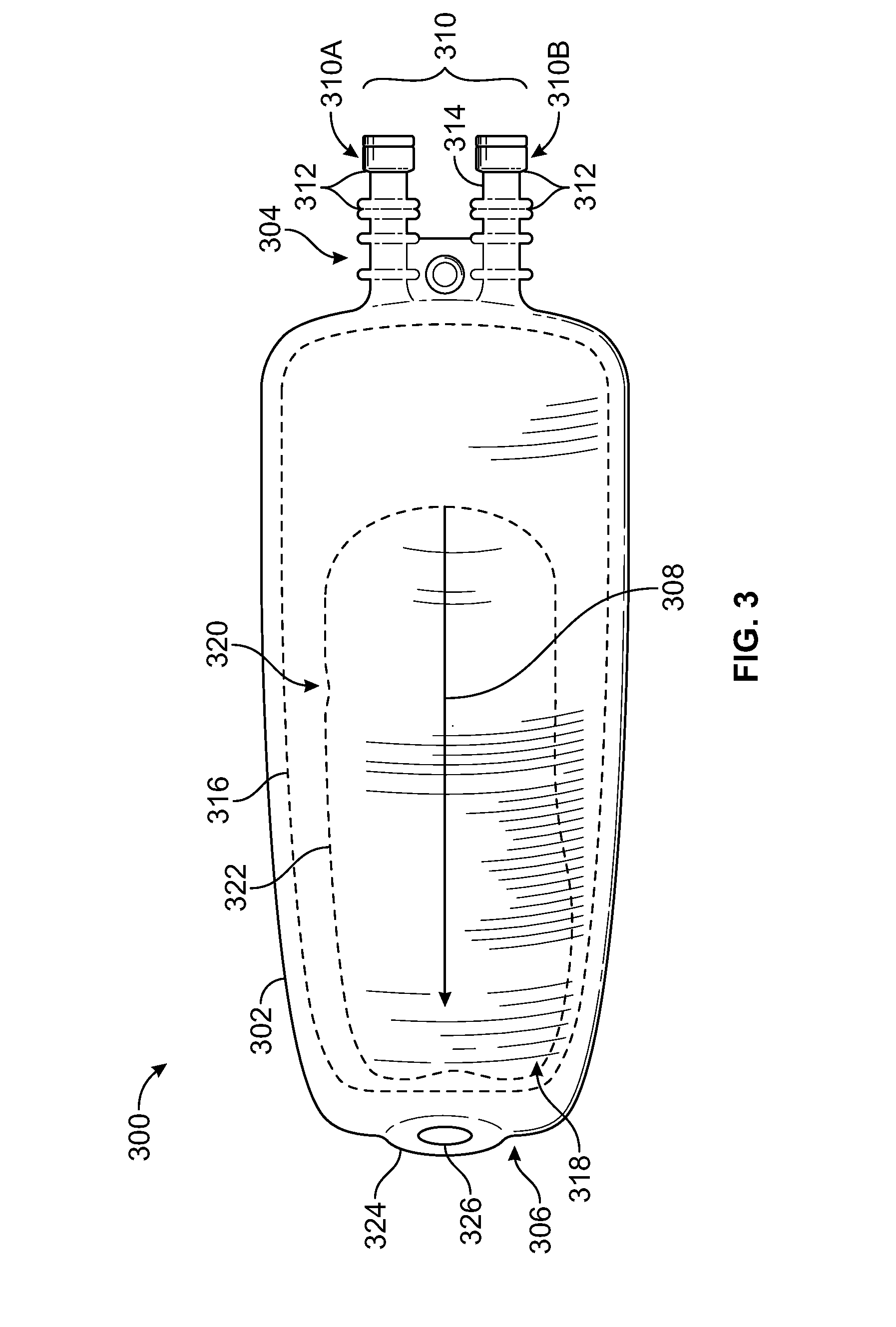
[0042]One or more embodiments of the inventive subject matter described herein relate to systems and methods for printing images on flexible bodies. The examples provided herein focus on inkjet printing an image including text and / or graphics, but additionally or alternatively may use one or more other techniques for printing the image. The examples also focus on printing the images on flexible fluid-containing bodies, such as intravenous therapy bags, or IV bags. Additionally or alternatively, however, one or more embodiments of the systems and methods described herein may be used to print on other objects, such as flexible sheets, flexible solid objects, and the like.

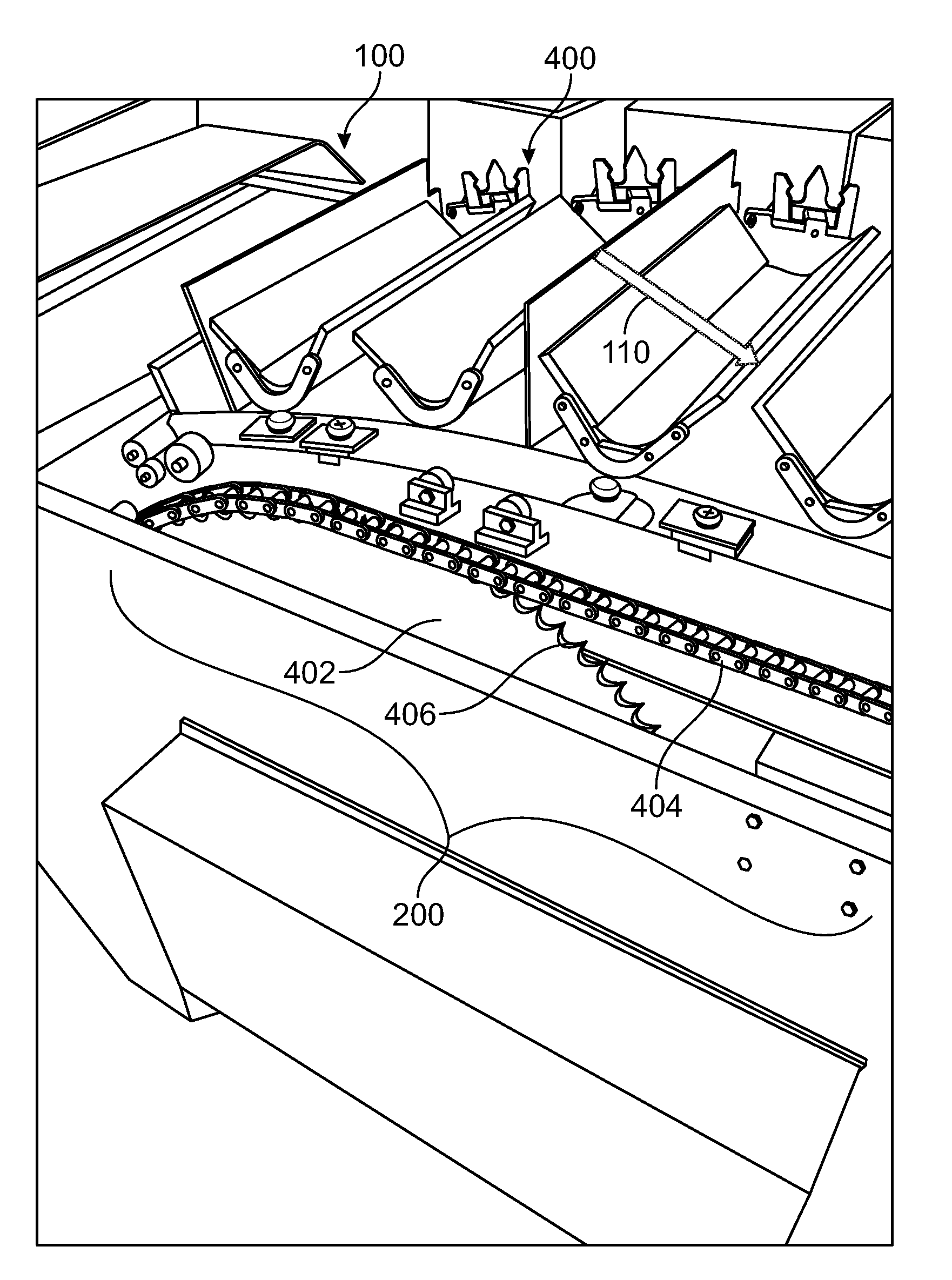
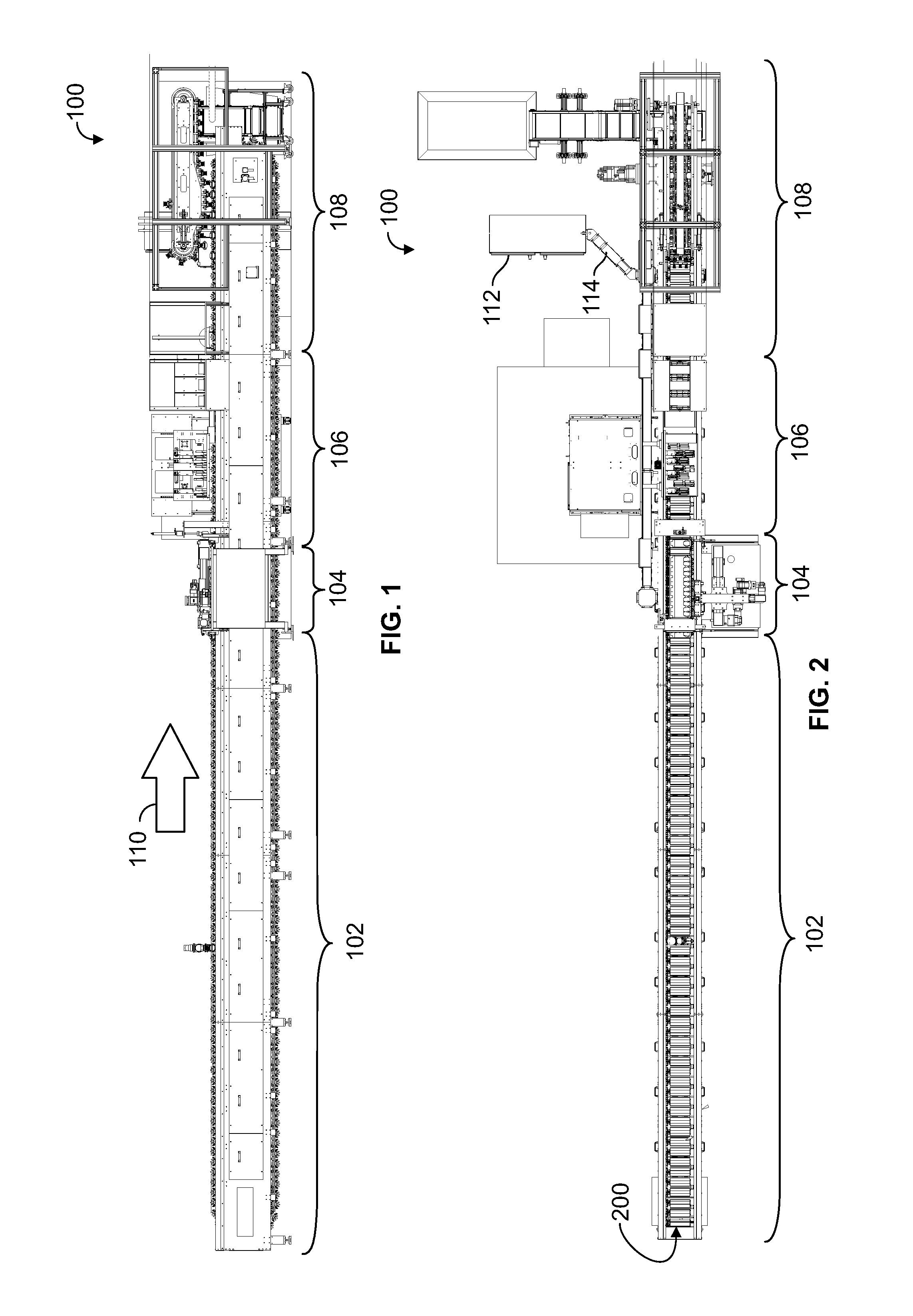
[0043]FIG. 1 illustrates a plan view of one embodiment of a printing system 100. FIG. 2 illustrates a top view of the printing system 100 shown in FIG. 1. The printing system 100 includes several stations that perform various operations in connection with manipulating flexible bodies (described below) in order to prod...


PUM


Abstract

A printing system includes carriage assemblies, a preparation station, a printing station, and a selection station. The carriage assemblies receive flexible bodies and are coupled to a conveyance assembly that moves the carriage assemblies along a direction of travel. The preparation station receives the flexible bodies from the loading station and manipulates the flexible bodies to at least partially flatten printing surfaces of the flexible bodies. The printing station prints images on the flexible bodies. The selection station examines the images on the flexible bodies and selects one or more of the flexible bodies based on the images. The selection station also individually grips and removes selected flexible bodies from the carriage assemblies and conveys the selected flexible bodies to a first collection location while the other flexible bodies remain on the carriage assemblies and are conveyed to a different, second collection location.

Description

CROSS-REFERENCE TO RELATED APPLICATIONS[0001]This application claims priority to U.S. Provisional Application No. 61 / 639,601, which was filed on 27 Apr. 2012, and is entitled “System And Method For Printing On A Flexible Body” (the “'601 application”). The entire subject matter of the '601 application is incorporated by reference.BACKGROUND[0002]A variety of objects have printed information on one or more surfaces of the objects. The information can be printed on the objects using one or more techniques. Some objects, however, can be difficult to print the information on surfaces of the objects. For example, flexible (e.g., non-rigid) objects can be difficult to print on due to the flexible nature of the objects and the tendency for the objects to shift, move, and the like, during the printing process.[0003]Some flexible objects present additional difficulties involved with printing on the objects. For example, three dimensional flexible objects can be difficult to print on if there...

Claims


Application Information

Patent Timeline
Patent Type & Authority Applications(United States)
IPC IPC(8): B41F21/00
CPCB41F21/00B41F17/001B41F17/002B41F17/006B41J3/407B41J3/40731B41J11/06
Inventor OLEJNICZAK, GREGORY B.PISCITELLO, MARC C.SOBASZEK, CHRISTOPHER J.VLCEK, GRAHAM P.O'NEIL, SEAN M.DELL'AQUILA, PETER P.WASZKOWIAK, STEVE
Owner ILLINOIS TOOL WORKS INC
Why Eureka
Eureka Blog
Learn More