Reticle unit, optical instrument, and rifle scope
- Summary
- Abstract
- Description
- Claims
- Application Information
AI Technical Summary
Benefits of technology
Problems solved by technology
Method used
Image

Examples
first embodiment
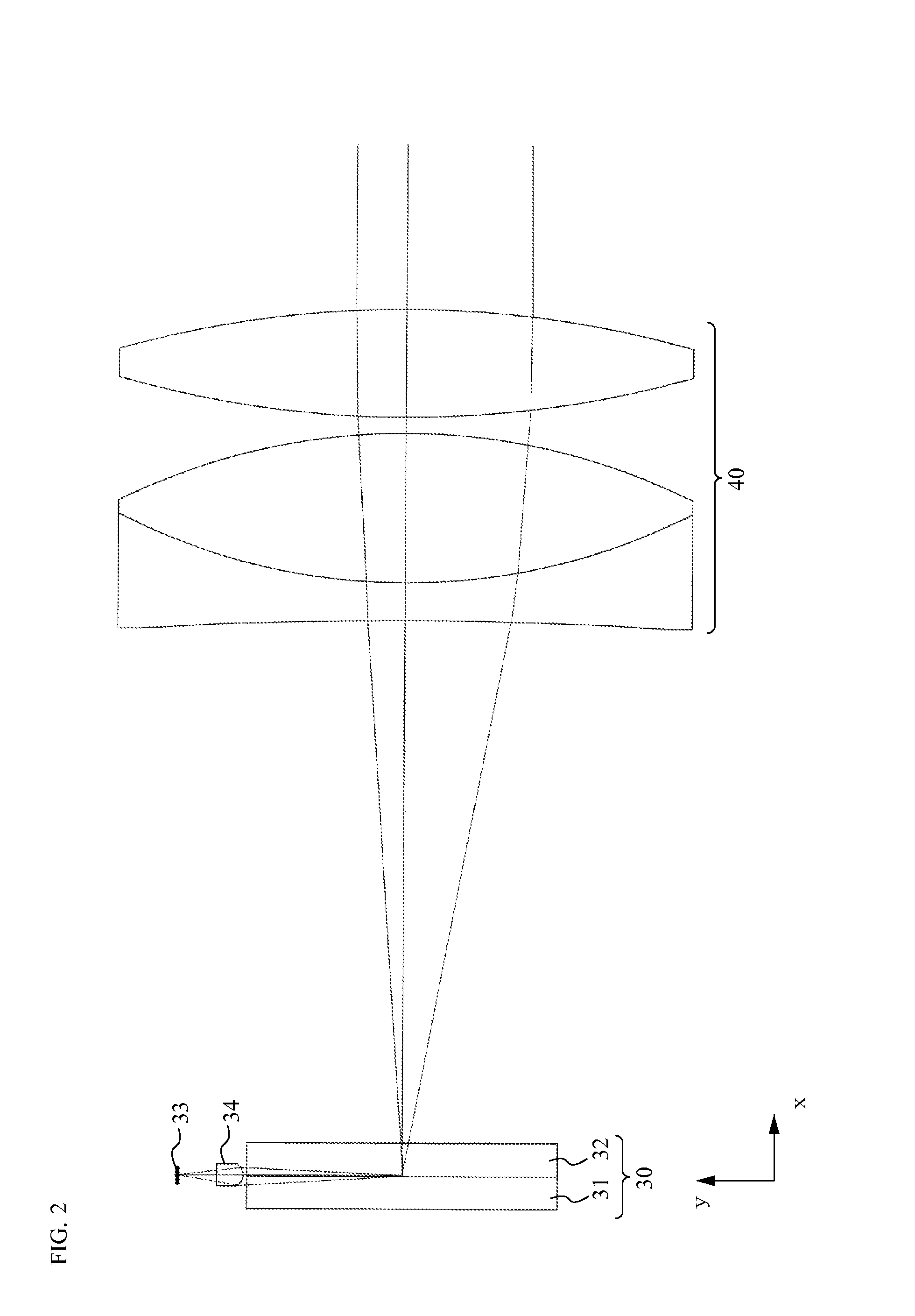
[0069]The reticle unit 30 according to a first embodiment will be described with reference to FIGS. 2 to 5. The reticle unit 30 includes: a reticle member 31 formed in a disc shape; a reflector 32 formed in a disc shape, arranged on the side of a surface (hereinafter, called “image side surface 31a”) closer to an image of the reticle member 31, and bonded to or arranged near the image side surface 31a; a light source 33 that emits illumination light; and a light collector (for example, condenser lens) 34 that collects the light from the light source 33. In the following description, as shown in FIGS. 2 to 4, an optical axis direction of the rifle scope 50 will be referred to as a z axis, and two orthogonal directions in a surface orthogonal to the z axis will be referred to as an x axis and a y axis. In this case, the optical axis of the light collector 34 that is a light collection optical system will be referred to as the y axis.
[0070]The reticle member 31 is formed by an optical ...
second embodiment
[0079]If the light source 33 and the light collector 34 are arranged laterally to the reticle member 31 and the reflector 32 to directly collect the illumination light from the light source 33 to the reflection surface 32c of the reflector 32 as shown in the first embodiment, part of the illumination light emitted from the light source 33 is incident on the reflection surface 32c at an angle that does not allow total reflection as shown in FIGS. 2 and 4 (that is, such light transmits through the reflection surface 32c). Specifically, in FIG. 4, part of the luminous flux (oblique line section on the right side) closer to the eyepiece 40 (right side) relative to the optical axis of the light source 33 and the light collector 34 exceeds the angle that allows the total reflection by the reflection surface 32c, and the part transmits through the reflection surface 32c. Therefore, as shown in FIGS. 2 and 4, the diameter of the luminous flux above the optical axis Z is thin, and the loss o...
third embodiment
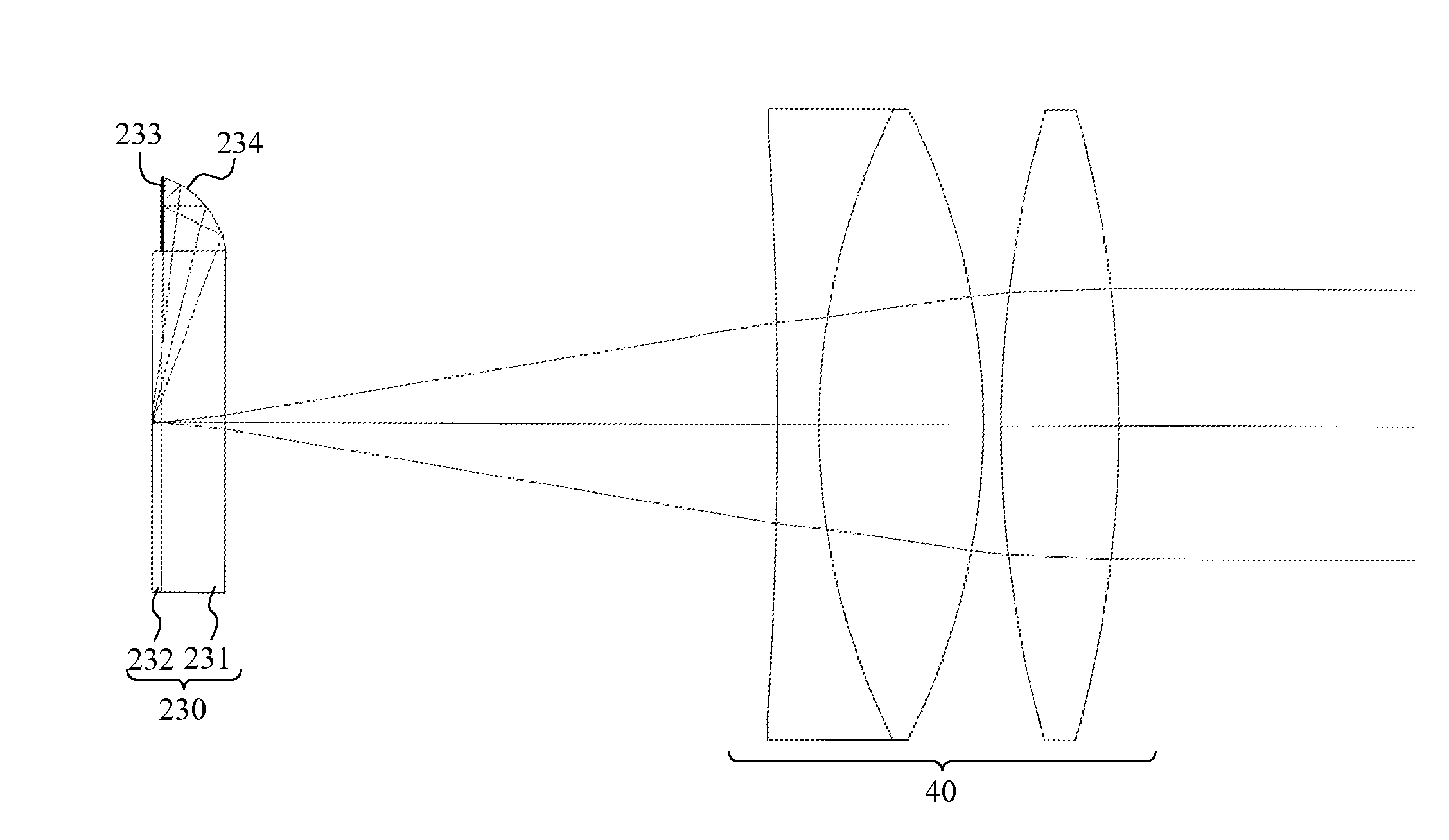
[0092]A reticle unit 230 according to a third embodiment will be described with reference to FIGS. 8 and 9. In the second embodiment, the configuration of attaching the light source 133 and the light collector 134 to the reflector 132 has been described. In the reticle unit 230 according to the third embodiment, a light source 233 and a light collector 234 are attached to the reticle member 231 as shown in FIG. 8, and a reflector 232 is further bonded to a surface on the object side of the reticle member 231. The reticle is formed on the surface on the object side of the reticle member 231, and a surface on the image side of the reflector 232 is bonded to the surface on the object side. A concave portion 232b is formed at a substantially central portion of an object surface 232a of the reflector 232, and part of a side surface forming the concave portion 232b forms a substantially flat reflection surface 232c (the concave portion 232b and the reflection surface 232c can have the sha...
PUM
 Abstract
Description
Claims
Application Information
 - Generate Ideas
- Intellectual Property
- Life Sciences
- Materials
- Tech Scout
- Unparalleled Data Quality
- Higher Quality Content
- 60% Fewer Hallucinations
Browse by: Latest US Patents, China's latest patents, Technical Efficacy Thesaurus, Application Domain, Technology Topic, Popular Technical Reports.
© 2025 PatSnap. All rights reserved.Legal|Privacy policy|Modern Slavery Act Transparency Statement|Sitemap|About US| Contact US: help@patsnap.com