
Color picture tube

Inactive Publication Date: 2007-06-07
MATSUSHITA TOSHIBA PICTURE DISPLAY CO LTD
View PDF8 Cites 0 Cited by
  • Summary
  • Abstract
  • Description
  • Claims
  • Application Information

AI Technical Summary

Benefits of technology

[0029] With the foregoing conventional problems in mind, it is an object of the present invention to provide a color picture tube that includes an inexpensive shadow mask with excellent formability and strength, has an excellent visibility and a compatibility with a conventional flat tube concerning mounting on a TV set, and is not susceptible to the deterioration in color purity due to doming. Also, it is a further object of the present invention to provide a color picture tube that allows the use of a more inexpensive reinforcing band by eliminating the need for a considerable increase in an embracing force of the reinforcing band.

Problems solved by technology

Therefore, the displacement amount of the landing positions of the electron beam also increases, thus deteriorating the color purity considerably.
Such an alloy has a coefficient of thermal expansion of 1 to 2×10⁻⁶ at 0° C. to 100° C., which is effective for suppressing doming; however, it entails high cost.
Furthermore, the iron-nickel alloy has a large elasticity after annealing, so that it is difficult to form a curved surface by press forming from a thin metal sheet that has been provided with an extremely large number of the electron beam passage apertures and to obtain a desired curved surface.
Therefore, it particularly is difficult to process the shadow mask 4 including the perforated region 4b with a large radius of curvature by press-forming this material.
In the case where press forming is insufficient and undesired stress remains in the shadow mask 4 after press forming, this residual stress changes the shape of the shadow mask 4 during the thermal process of the color picture tube, which leads to the displacement of the landing positions of the electron beams, resulting in significant deterioration in the color purity.
However, the coefficient of thermal expansion of such a material mainly containing high-purity iron is as high as about 12×10−6 at 0° C. to 100° C., which is disadvantageous for doming.
Particularly, in the case of applying this material to a color picture tube having the panel 1 whose useful portion 1a has the substantially flat outer surface, there arises a serious problem such as the considerable deterioration in color purity.
However, the radius of curvature of the inner surface is not sufficient to suppress effectively the above-described various problems regarding the shadow mask.
Thus, there has been a significant problem especially in the case of using a shadow mask formed of an inexpensive iron material.
However, the radius of curvature of its inner surface is not small enough to suppress the above-described various problems effectively.
In particular, a very large thermal stress is generated in the thick portion of the panel 1, causing a problem that the envelope 9 is broken.
As a result, there also has been a problem that the brightness of the image becomes nonuniform such that the central portion of a screen becomes bright and the peripheral portion thereof becomes dark.
Therefore, it is difficult to make the difference in thickness between the central portion and the peripheral portion of the useful portion 1a of the panel 1 larger than that in the conventional case, and there has been a limitation on the reduction of the radius of curvature of the inner surface of the panel 1 whose useful portion 1a has a flat outer surface.
Then, as described above, when the iron material that is inexpensive and has excellent formability is used as the material for the shadow mask 4, its large coefficient of thermal expansion causes a still larger displacement amount of the electron beam landing positions due to the thermal expansion of the shadow mask 4, thus deteriorating the color purity further.
However, such a color picture tube is not compatible with the demand for a flatter outer surface of the useful portion 1a of the panel 1.
In other words, it is not possible to ensure compatibility of the front cabinet of the TV set with the conventional flat tube.
However, when the outer surface of the useful portion 1a of the panel 1 is flattened, the effect of the reinforcing band 12 of deforming the useful portion 1a of the panel 1 such that its central portion bulges outward cannot be obtained easily, necessitating a reinforcing band generating a larger embracing force.

Method used


Image

  • Color picture tube
  • Color picture tube
  • Color picture tube

Examples


example

[0074] The following is a description of an example of applying the present invention to a 68-cm-diagonal color picture tube with an aspect ratio of 4:3 (hereinafter, referred to as “Example”).

[0075] A useful portion 1a of a panel 1 of the color picture tube according to the present Example had a thickness T0 at its center P0 of 11.5 mm and a transmittance at the center P0 of 54%. As a material for a shadow mask 4, aluminum killed decarbonized steel made of high-purity iron having a coefficient of thermal expansion of 12×10−6 at 0° C. to 100° C. was used.

[0076] For comparison, the conventional flat tube having a panel 1 whose useful portion 1a had a curved outer surface with a uniform radius of curvature was produced (hereinafter, referred to as “Conventional Example”).

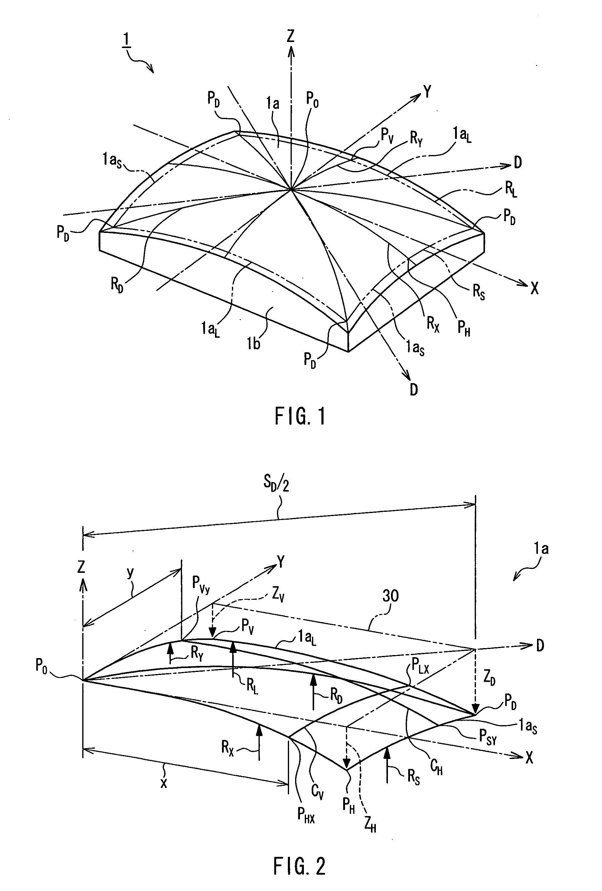
[0077] On the outer surface of the useful portion 1a of the panel 1, a radius of curvature along its diagonal axis D was indicated by RD, a radius of curvature along its long side 1aL was indicated by RL, a radius ...


PUM


Abstract

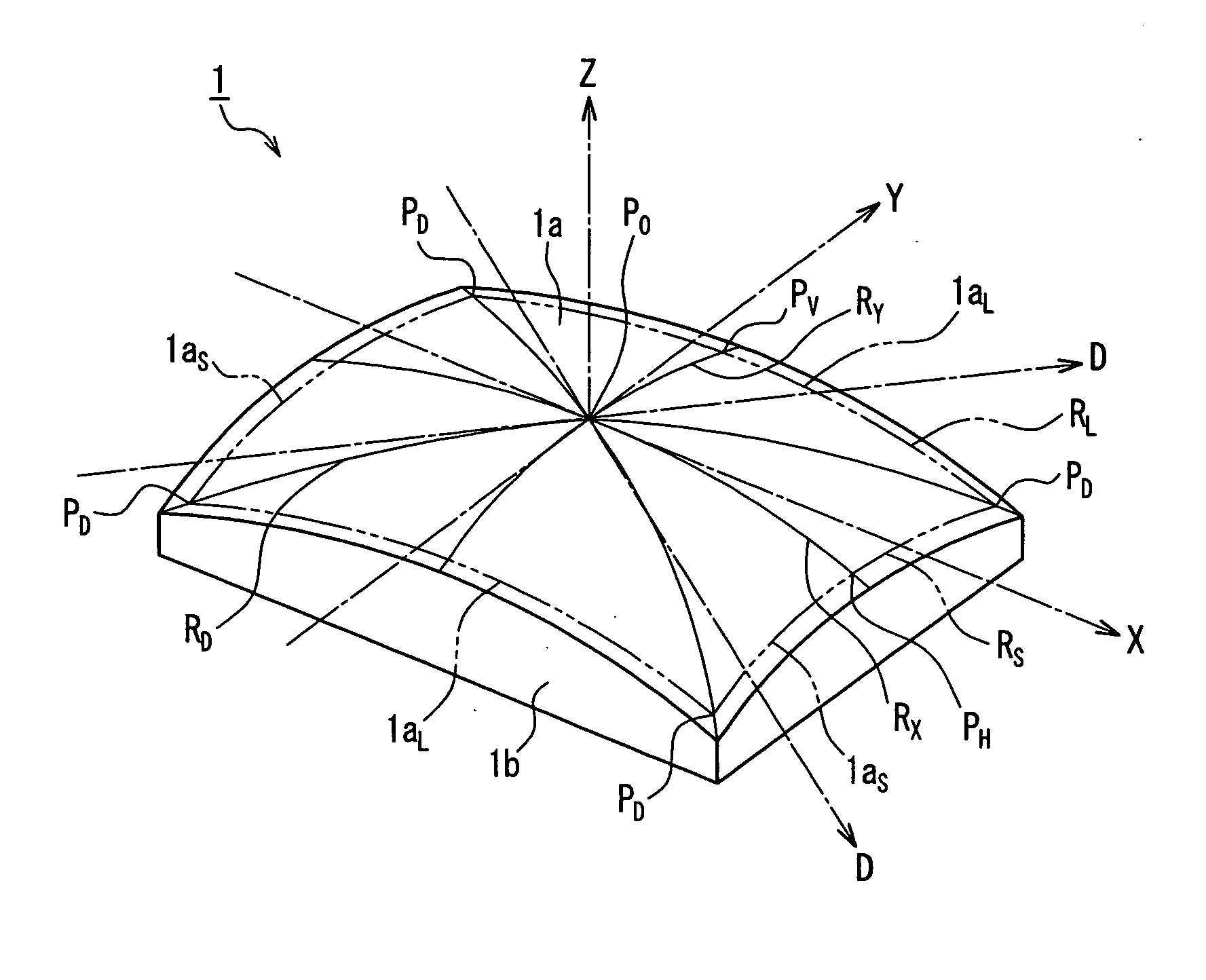
The radii of curvature RD, RS and RL along a diagonal axis, a short side and a long side of an outer surface of a useful portion of a panel whose inner surface is provided with a phosphor screen satisfy RD≧10 m, RS>RD, and RL>RD. This makes it possible to provide a color picture tube that has an excellent visibility and is not susceptible to the deterioration in color purity due to doming, while including a shadow mask with excellent formability and strength.

Description

BACKGROUND OF THE INVENTION [0001] 1. Field of the Invention [0002] The present invention relates to a color picture tube including a shadow mask. [0003] 2. Description of Related Art [0004] In general, as shown in FIG. 7, a color picture tube has a glass envelope 9 including a substantially rectangular panel 1 in which a lateral wall portion 1b is provided on the periphery of a useful portion 1a having a curved surface, and a funnel 2 in a funnel shape joined to the lateral wall portion 1b. An inner surface of the useful portion 1a of the panel 1 is provided with a substantially rectangular phosphor screen 3 formed of black non-light-emitting material layers and phosphors of three colors, i.e., green, blue and red that are filled in gaps between these black non-light-emitting material layers. Each of the phosphors is formed in a stripe shape extending along a short side direction, and a large number of these phosphor stripes are arranged in a long side direction. [0005] Further, a ...

Claims


Application Information

Patent Timeline
IPC IPC(8): H01J29/86
CPCH01J29/86H01J2229/862
Inventor MURAI, TAKASHIKOJIMA, TADAHIRONAKAYAMA, TAKESHISETO, NOBUYUKI
Owner MATSUSHITA TOSHIBA PICTURE DISPLAY CO LTD
Learn More