
Low-Frequency Seismic-While-Drilling Source

a low-frequency seismic and source technology, applied in the field of seismic pulse generation and downhole drilling operations, can solve the problems of ineffective pdc bits commonly used for drilling, ineffective soft formation soft formation drill bit sources, etc., and achieve the effect of reducing the impulse cycle rate, minimizing source noise, and increasing the pulse duration

Inactive Publication Date: 2013-10-31
TEMPRESS TECH
View PDF18 Cites 10 Cited by
  • Summary
  • Abstract
  • Description
  • Claims
  • Application Information

AI Technical Summary

Benefits of technology

The invention describes a way to generate seismic waves that have a longer pulse duration and fewer pulses, which reduces the noise and improves the accuracy of the data collected from the ground. This is achieved by using a special drilling tool assembly that includes a pulse generation section and an acoustic baffling section. This tool can help to better understand the geology and position of drilling equipment during drilling operations.

Problems solved by technology

Drill bit sources are not effective in soft formations and PDC bits commonly used for drilling are not effective at all.

Method used


Image

  • Low-Frequency Seismic-While-Drilling Source
  • Low-Frequency Seismic-While-Drilling Source
  • Low-Frequency Seismic-While-Drilling Source

Examples


Embodiment Construction

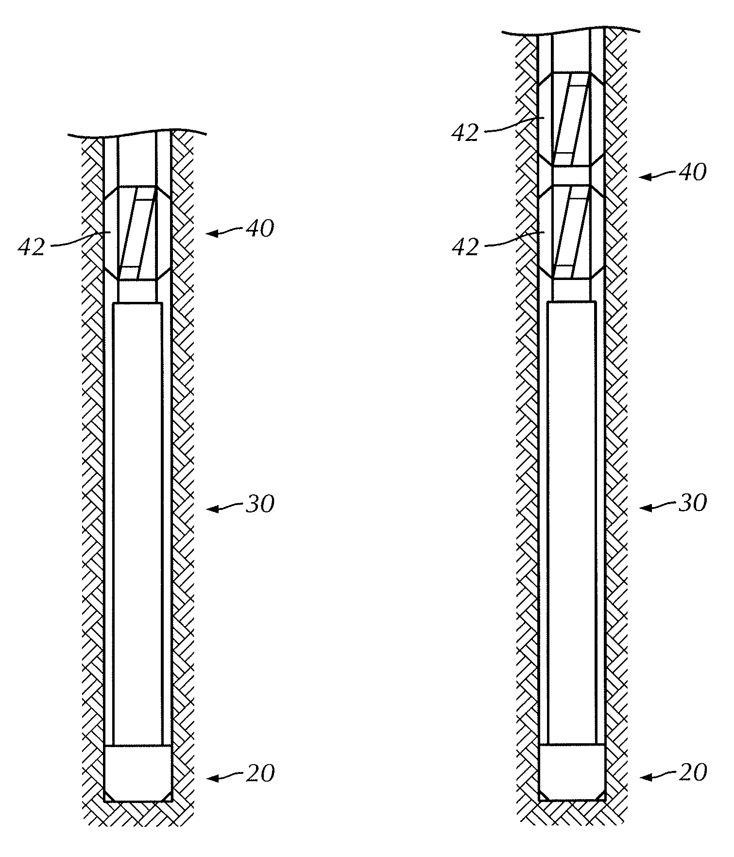
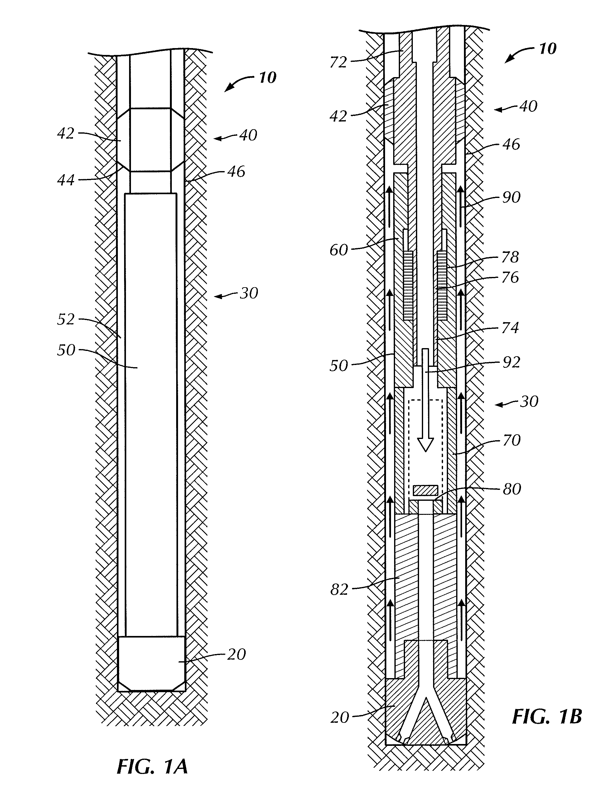
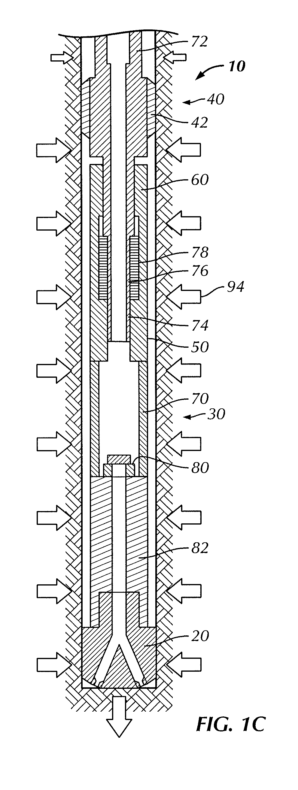
[0022]Exemplary embodiments are illustrated in referenced Figures of the drawings. It is intended that the embodiments and Figures disclosed herein are to be considered illustrative rather than restrictive. No limitation on the scope of the technology that follows is to be imputed to the examples shown in the drawings and discussed herein.

[0023]Those skilled in the art will recognize that the seismic energy radiated by a source is determined by the square of the rate at which the force is applied, as well as the source dimensions and other factors. A source with a rapid rise time is thus critical for generating a signal with high energy that will be transmitted to surface receivers. The seismic source described in U.S. Pat. No. 7,139,219 and the hydraulic pulse valve assembly described in U.S. patent application Ser. No. 12 / 957,049 both generate pressure in the borehole annulus and axial force pulses with a rise time on the order of one millisecond and are therefore capable of gener...


PUM


Abstract

A bottom hole assembly is configured with a drill bit section connected to a pulse generation section. The pulse generation section includes a relatively long external housing, the particular housing length being selected for the particular drilling location. The long external housing is positioned closely adjacent to the borehole sidewalls to thereby create a high speed flow course between the external walls of the housing and the borehole sidewalls. The long external housing includes a valve cartridge assembly and optionally a shock sub decoupler. While in operation, the valve cartridge assembly continuously cycles and uses downhole pressure to thereby generate seismic signal pulses that propagate to geophones or other similar sensors on the surface. The amount of bypass allowed through the valve assembly is selectable in combination with the long external housing length and width to achieve the desired pulse characteristics. The bottom hole assembly optionally includes an acoustic baffle to attenuate wave propagation going up the drill string.

Description

RELATED APPLICATIONS[0001]The present application claims the benefit of U.S. Provisional Patent Application, Ser. No. 61 / 638,456 filed on Apr. 25, 2012 and U.S. Non-Provisional patent application Ser. No. 12 / 957,049 filed on Nov. 30, 2010, each incorporated herein by reference in its entirety.BACKGROUND[0002]1. Field of the Invention[0003]The present invention relates to seismic pulse generation and downhole drilling operations.[0004]2. Description of the Related Art[0005]Downhole drilling tool assemblies including mud pulsers that transmit data to surface sensors on the drillstring have seen use in drilling operations for some time. In downhole drilling and especially in lateral drilling it is useful to track the position of the drilling assembly. Over time drilling operations have seen drilling to greater depths through a larger variety of geological formations. These factors and others continue to create the need for more advanced seismic source tools, seismic detectors having gr...

Claims


Application Information

Patent Timeline
IPC IPC(8): G01V1/133
CPCG01V1/133
Inventor KOLLE, JACK J.
Owner TEMPRESS TECH
Learn More