Electrical power transfer indicator system and method

a technology of power transfer indicator and indicator system, which is applied in the direction of fault location by conductor type, measurement using ac-dc conversion, instruments, etc., can solve problems such as unwanted ground fault, and achieve the effect of increasing the magnitude of the current of the pulse and increasing the duration of the puls

Active Publication Date: 2014-06-24
BIERER WALTER S
View PDF16 Cites 2 Cited by
  • Summary
  • Abstract
  • Description
  • Claims
  • Application Information

AI Technical Summary

Benefits of technology

[0006]The system includes a controller having two leads and a rectifier. The controller and rectifier can be connected using the two leads to two power lines in an electrical power system. When connected to power lines, the two leads are in series with the rectifier between them. The leads may carry fuses, and ideally carry separate fuses. The rectifier has a non-conducting state and a conducting state, and is controlled by a processor which can activate the rectifier and cause a very near to a short circuit in the two electrical power lines. When the two power lines are shorted near the end of the positive voltage cycle, the rectifier will conduct but only briefly from when it is activated by the processor until the voltage crosses from positive to negative. The rectifier will of course not conduct when the voltage is negative. Accordingly, the length of the resulting direct current pulse is determined by the timing of the processor's signal to the rectifier to conduct but is intentionally made short in duration. Increasing the duration of the pulse, by having the processor initiate conduction across the rectifier incrementally earlier in the alternating voltage cycle, also increases the magnitude of the current of the pulse. Pulsing may be continued as long as needed and its duration may be adjusted as desired.

Problems solved by technology

For example, by detecting the current pulse on a power line one kilometer from where the controller caused the pulse but not detecting it on that same line two kilometers away, one may learn that there is an unwanted ground fault somewhere between the first and second kilometers of power line.

Method used


Image

  • Electrical power transfer indicator system and method
  • Electrical power transfer indicator system and method
  • Electrical power transfer indicator system and method

Examples


Embodiment Construction

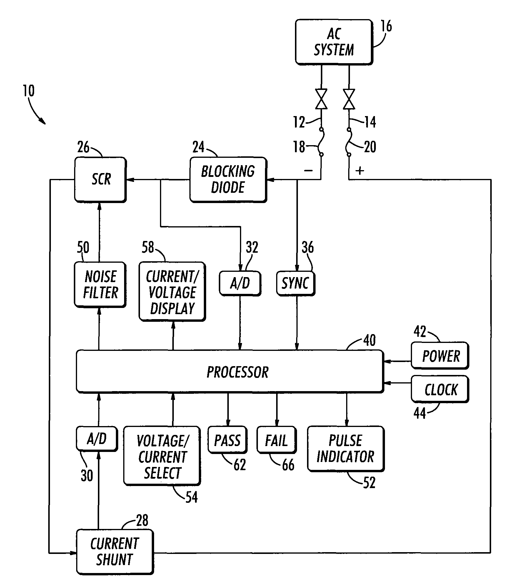
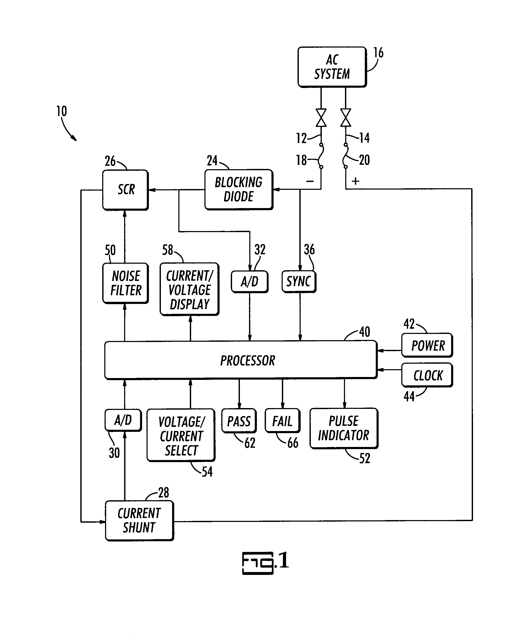
[0020]The present invention is a system and method for indicating electrical power transfer. The present system and method is intended to be used with an electrical power system that operates on sinusoidally alternating current and, with suitable adaptations, on systems that transfer electrical power from high power transmission lines to household power cables. The term “indicating” ranges in meaning, depending on the particular configuration of and method for using the present system, from simply confirming the transfer of electrical power (or not), to determining the completeness of the transfer (whether all or only a portion of the power is being transferred), to quantifying the percent of the power consumed by the load that is provided by a particular generator. The phrases “power line” and “power cable” refer to electrical conductors running between end points. The term “short” in the context of a short circuit will be used herein not in the literal sense but in the sense of ve...


PUM


Abstract

Power transfer over power lines is indicated using a controller to short power lines briefly near the end of the positive portion of the alternating voltage cycle of a distant power generation source using a silicon-controlled rectifier thereby creating current pulses from the voltage produced by that source and at a frequency consistent with the source's electric system frequency. The pulse can be detected and measured on other parts of the same circuit using a probe. The controller and probe may be used for locating cables in the same electrical circuit, sorting particular cables in the same circuit from others cables, verifying the condition of cables, determining the source and load feeds on the primary side of a transformer from the low side of the transformer, locating unwanted ground faults, and determining the portion of the electrical load provided by each of plural generation plants.

Description

PRIORITY CLAIM[0001]Priority is claimed to U.S. provisional patent application Ser. No. 61 / 362,416 filed 8 Jul. 2010, which is incorporated herein in its entirety by reference.BACKGROUND OF THE INVENTION[0002]In a modern electrical power grid, power is distributed from power lines through transformers to consumers of power, such as industrial facilities commercial facilities, businesses and residences. The resulting distribution network often requires those who service it to identify which power line is the right one and whether it is functioning properly. For example, there may be an unwanted ground somewhere on a floating delta three-phase power line that is miles long. Lineman must determine which line and where on that line the ground has occurred. In another example, a homeowner may complain about unsteady electrical power from an outlet. The source of the problem may be in the power supply between the outlet and the fuse box or between the fuse box and the nearest transformer,...

Claims


Application Information

Patent Timeline
Patent Type & Authority Patents(United States)
IPC IPC(8): G01R19/22
CPCG01R19/22G01R31/086H02J13/0024H02J13/00009H02J13/00034Y02E60/00Y04S10/52Y04S40/121
Inventor BIERER, WALTER, S.
Owner BIERER WALTER S
Why Eureka
Try Eureka