End point detection for back contact solar cell laser via drilling

a solar cell and laser technology, applied in the field can solve the problems of limited laser processing in crystalline silicon solar cell fabrication, significant fabrication challenges presented for the back side, and difficult laser processing, particularly laser ablation and drilling, so as to improve the laser processing method of back contact solar cells and eliminate or reduce the cost and fabrication disadvantages

Inactive Publication Date: 2013-10-31
BEAMREACH SOLAR INC
View PDF6 Cites 21 Cited by
  • Summary
  • Abstract
  • Description
  • Claims
  • Application Information

AI Technical Summary

Benefits of technology

[0011]Therefore, a need has arisen for improved back contact solar cell laser processing methods. In accordance with the disclosed subject matter, methods and structures for fabricating photovoltaic back contact solar cells having multi-level metallization using laser via drilling end point detection are disclosed which substantially eliminate or reduce the cost and fabrication disadvantages associated with previously developed back contact solar cell laser processing methods.

Problems solved by technology

However, significant fabrication challenges are presented for forming back side metallization patterns having both emitter and base contacts which are often exacerbated when processing sub-50-micron thick silicon substrates.
Despite these advantages, the use of laser processing in crystalline silicon solar cell fabrication has been limited because laser processes that provide high performance cells have not been developed.
Solar cells often comprise varying and extremely sensitive layers of materials which makes laser processing difficult, particularly laser ablation and drilling.

Method used


Image

  • End point detection for back contact solar cell laser via drilling
  • End point detection for back contact solar cell laser via drilling
  • End point detection for back contact solar cell laser via drilling

Examples


Embodiment Construction

[0030]The following description is not to be taken in a limiting sense, but is made for the purpose of describing the general principles of the present disclosure. The scope of the present disclosure should be determined with reference to the claims. Exemplary embodiments of the present disclosure are illustrated in the drawings, like numbers being used to refer to like and corresponding parts of the various drawings.

[0031]Importantly, the exemplary dimensions and calculations disclosed for embodiments are provided both as detailed descriptions for specific embodiments and to be used as general guidelines when forming and designing solar cells in accordance with the disclosed subject matter.

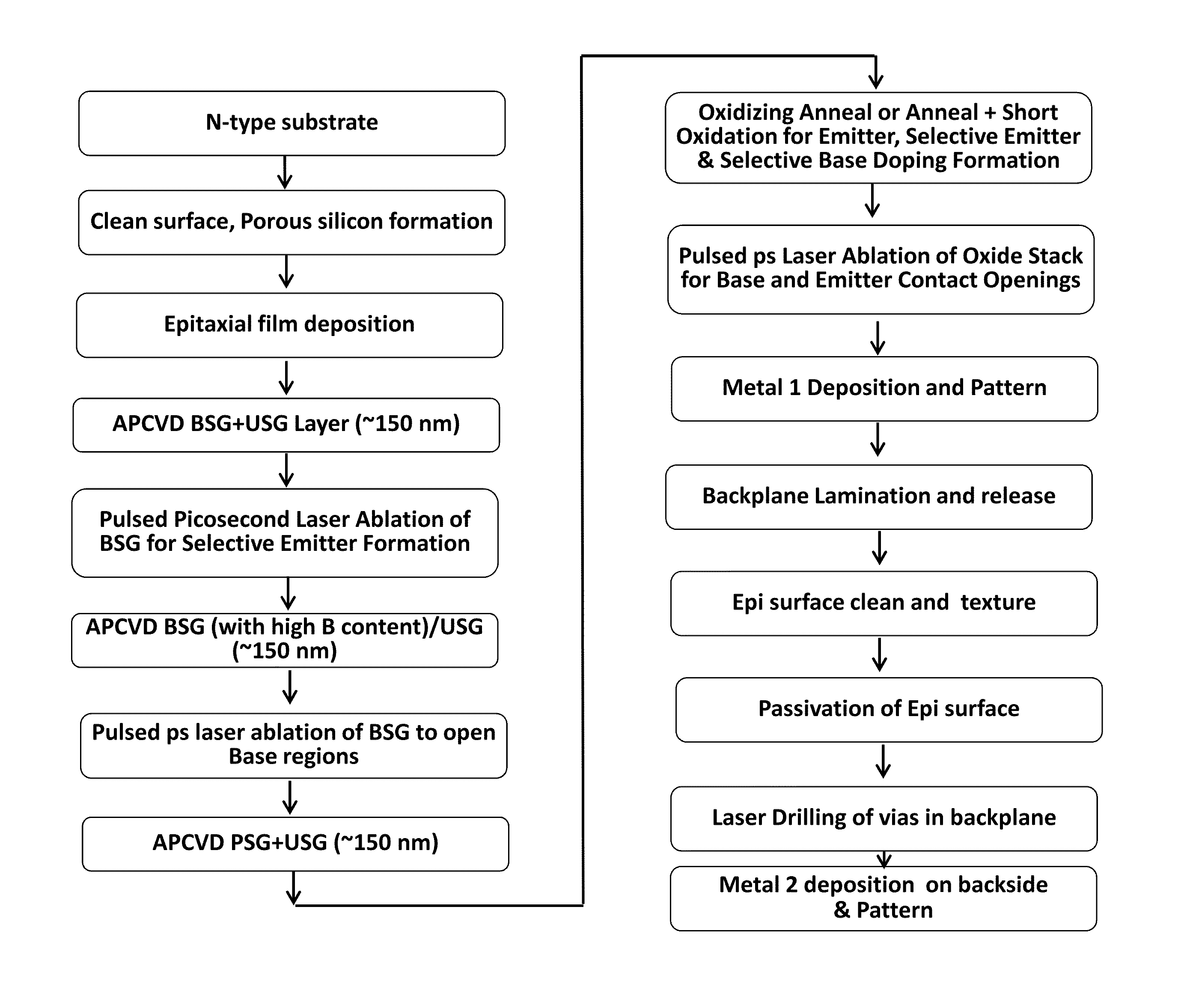
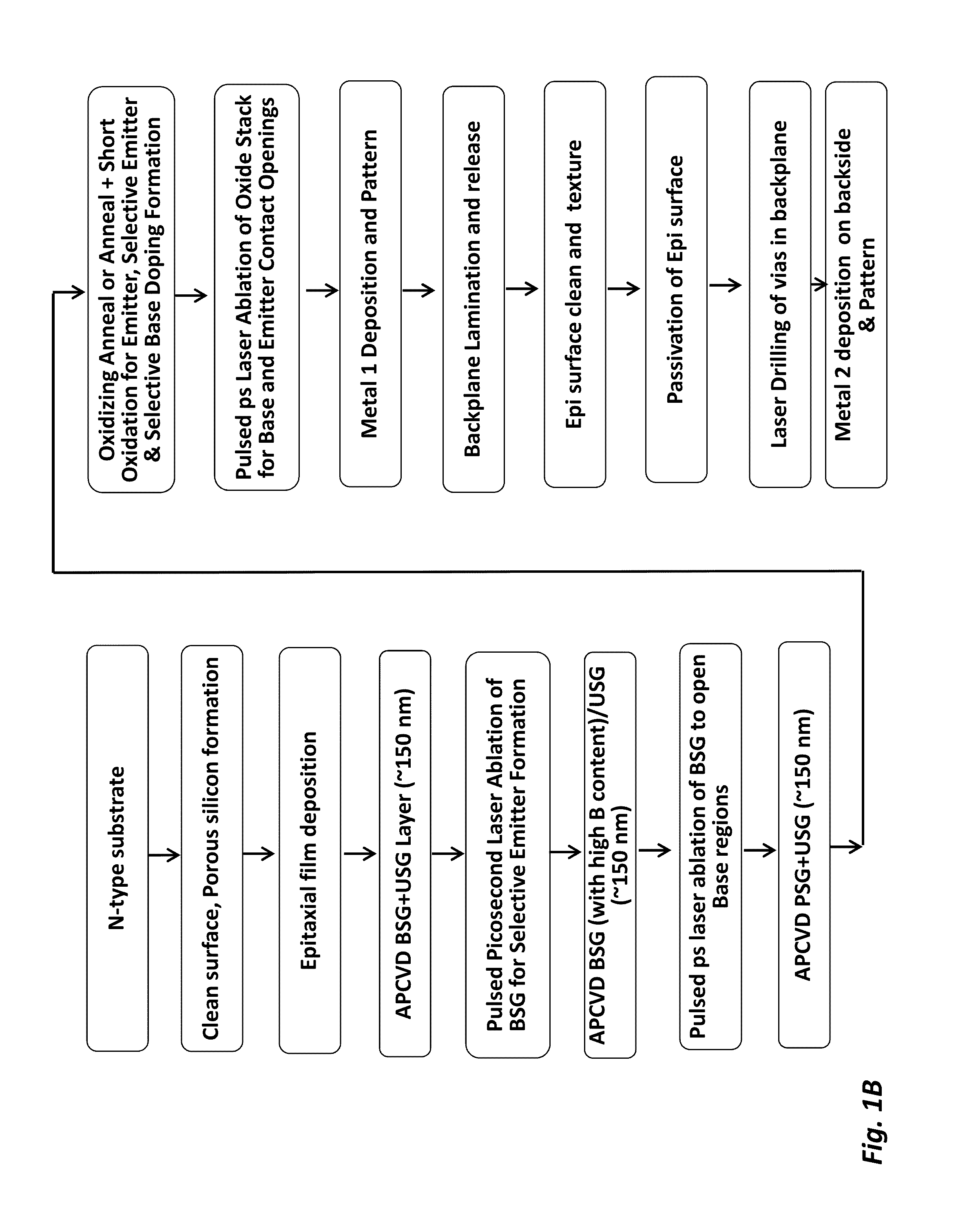
[0032]And although the present disclosure is described with reference to specific embodiments, such as back contact solar cells using monocrystalline silicon substrates having a thickness in the range of 10 to 200 microns and other described fabrication materials metallization layers, one skilled...


PUM

PropertyMeasurementUnit
pulse lengthaaaaaaaaaa
thicknessaaaaaaaaaa
thicknessaaaaaaaaaa

Abstract

Methods and structures for fabricating photovoltaic back contact solar cells having multi-level metallization using laser via drilling end point detection are provided.

Description

CROSS-REFERENCE TO RELATED APPLICATIONS[0001]This application claims the benefit of U.S. Provisional Pat. App. Nos. 61 / 617,033 filed on Mar. 28, 2012 and 61 / 725,434 filed Nov. 12, 2012, which are hereby incorporated by reference in their entirety.[0002]This application is a continuation-in-part of U.S. patent application Ser. Nos. 13 / 204,626 filed on Aug. 5, 2011, 13 / 271,212 filed Oct. 10, 2011, and 13 / 807,631 filed Dec. 28, 2012, which are hereby incorporated by reference in their entirety.FIELD OF THE INVENTION[0003]The present disclosure relates in general to the fields of solar photovoltaic (PV) cells, and more particularly to back contact solar cells.BACKGROUND[0004]Photovoltaic solar cells, including crystalline silicon solar cells, may be categorized as front-contact or back-contact cells based on the locations of the two polarities of the solar cell metal electrodes (emitter and base electrodes). Conventional front-contact cells have emitter electrode contacts on the cell fr...

Claims


Application Information

Patent Timeline
Patent Type & Authority Applications(United States)
IPC IPC(8): H01L31/18
CPCH01L31/186H01L31/022441H01L31/0516H01L31/0682H01L31/18H01L31/1892B23K26/009B23K26/03B23K26/032Y02E10/547B23K26/0622B23K26/40B23K26/389B23K2103/172
Inventor RANA, VIRENDRA V.MOSLEHI, MEHRDAD M.ANBALAGAN, PRANAVDESHAZER, HEATHERCOUTANT, SOLENERATTLE, BENJAMIN E.KRAMER, KARL-JOSEFKAPUR, PAWAN
Owner BEAMREACH SOLAR INC
Why Eureka
Try Eureka