
Methods For Providing A Bonded-Particle Model In Computer Aided Engineering System

a computer-aided engineering and model technology, applied in the field of computer-aided engineering analysis, can solve the problems of inability to meet macro-level simulation requirements, drawbacks or shortcomings of prior art approaches, and no integrated technique to bridge the continuum mechanics and fractured particles

Active Publication Date: 2013-10-31
ANSYS
View PDF2 Cites 6 Cited by
  • Summary
  • Abstract
  • Description
  • Claims
  • Application Information

AI Technical Summary

Benefits of technology

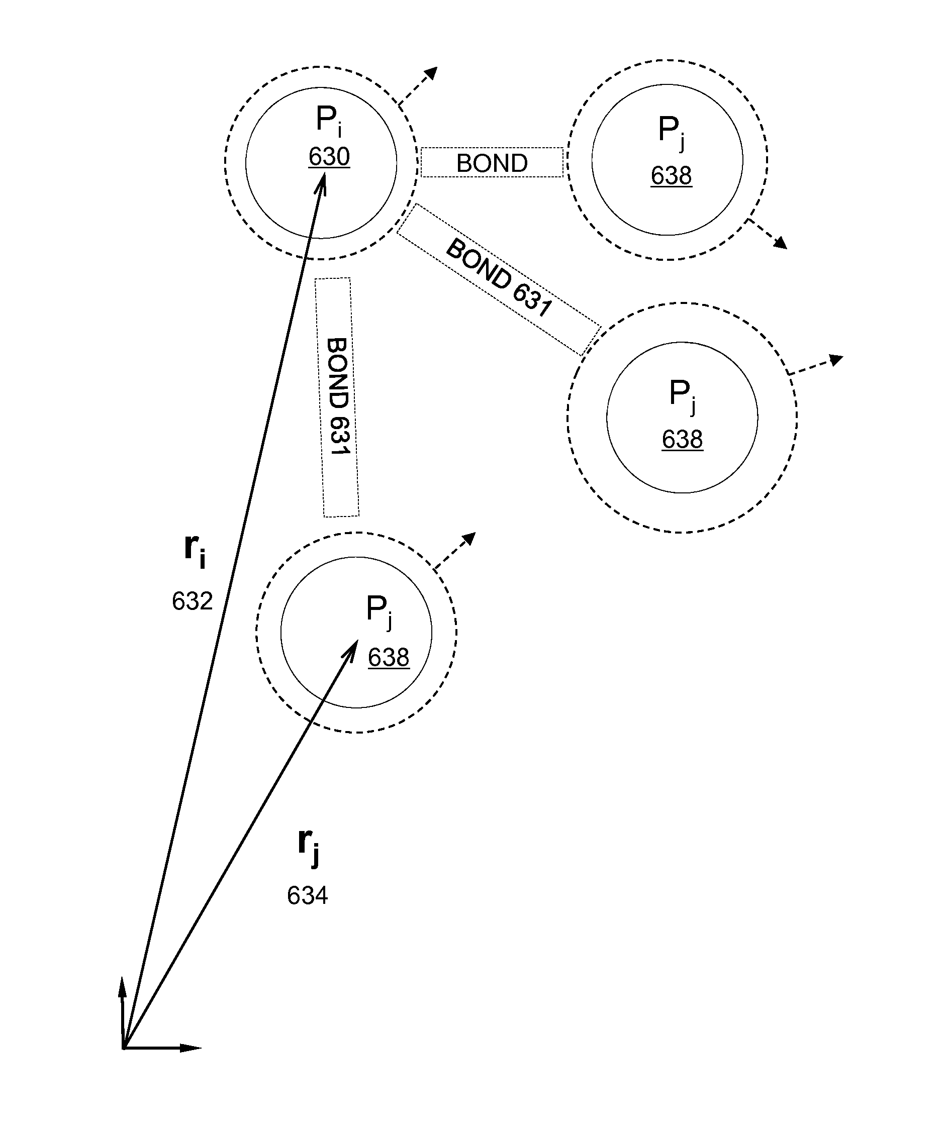
The present invention is about a system and method for simulating the behavior of a physical domain made of brittle material. The domain is represented by a plurality of discrete particles, which are connected to each other through bonds. The bonded-particle model is used to represent the physical properties of the domain, including material properties and fracture energy release rate. The model allows for individual movement of each particle and does not involve any differential or integral operations. The technical effect of this invention is to provide a more accurate and efficient means for simulating the behavior of physical domains made of brittle materials.

Problems solved by technology

In other disciplines, molecular dynamics (MD) have been used for determining the forces and energy atoms and molecules for simulations spanning nano-level to micro-level, which are not suitable for macro-level simulations.
However, there are drawbacks or shortcomings in prior art approaches.
In particular, there is no integrated technique to bridge the continuum mechanics and fractured particles after the continuum has been damaged.
Many ad hoc methods have been proposed, but none of these prior art approaches is satisfactory.
For example, one of the prior art approaches assumes the forces acting on particles are axial only, hence not being able to simulate a domain having any relative shear deformation or lateral deformation correctly.

Method used


Image

  • Methods For Providing A Bonded-Particle Model In Computer Aided Engineering System
  • Methods For Providing A Bonded-Particle Model In Computer Aided Engineering System
  • Methods For Providing A Bonded-Particle Model In Computer Aided Engineering System

Examples


Embodiment Construction

[0027]In the following description, numerous specific details are set forth in order to provide a thorough understanding of the present invention. However, it will become obvious to those skilled in the art that the present invention may be practiced without these specific details. The descriptions and representations herein are the common means used by those experienced or skilled in the art to most effectively convey the substance of their work to others skilled in the art. In other instances, well-known methods, procedures, components, and circuitry have not been described in detail to avoid unnecessarily obscuring aspects of the present invention.

[0028]Reference herein to “one embodiment” or “an embodiment” means that a particular feature, structure, or characteristic described in connection with the embodiment can be included in at least one embodiment of the invention. The appearances of the phrase “in one embodiment” in various places in the specification are not necessarily ...


PUM


Abstract

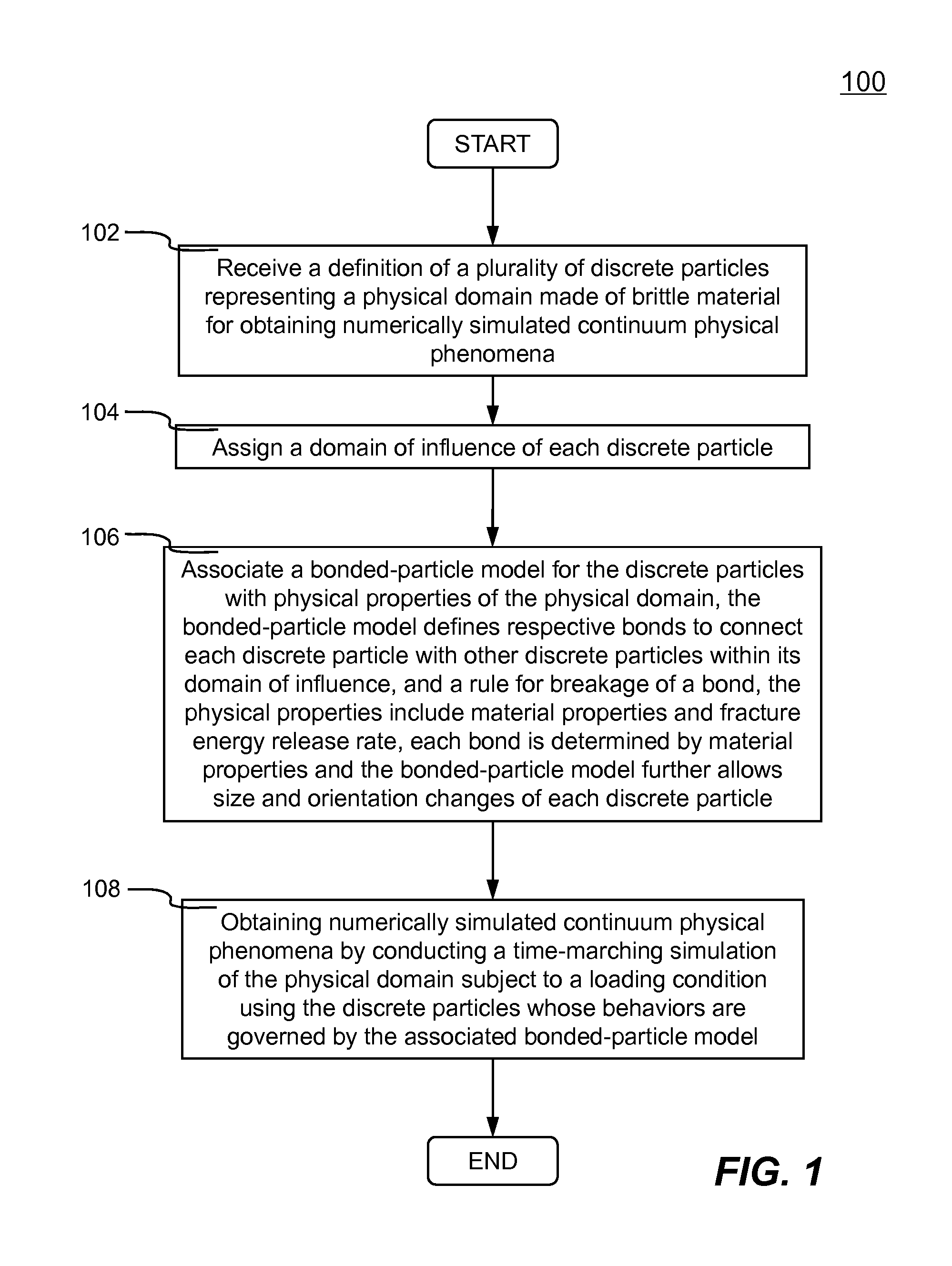
Systems and methods of providing bonded-particle model amongst a plurality of discrete particles representing a physical domain made of brittle material in a time-marching simulation to obtain numerically simulated continuum physical phenomena are disclosed. A physical domain is represented by a plurality of discrete particles. A domain of influence is assigned to each discrete particle and a bonded-particle model is created for the discrete particles. Respective bonds are established to connect each discrete particle to all other discrete particles within its domain of influence. The bonded-particle model further defines a rule for breakage of a bond. Continuum physical phenomena of the physical domain are numerically represented through a set of formula such that a time-marching simulation of the physical domain can be conducted. Physical properties include material properties and fracture energy release rate. Finally, the bonded-particle model allows size and orientation changes of each discrete particle.

Description

FIELD OF THE INVENTION[0001]The present invention generally relates to computer-aided engineering analysis, more particularly to systems and methods of providing a bonded-particle model amongst a plurality of discrete particles that represents a physical domain made of brittle material in a time-marching simulation to obtain numerically simulated physical phenomena.BACKGROUND OF THE INVENTION[0002]Many modern engineering analyses are performed with the aid of a computer system. One of such computer aided engineering (CAE) analyses is referred to as discrete element method (DEM) or distinct element method, which is generally used for numerically simulating the motion of a large number of discrete particles. With advances in computing power and numerical algorithms for nearest neighbor sorting, it has become possible to numerically simulate millions of discrete particles. Today DEM is becoming widely accepted as an effective method of addressing engineering problems in granular and di...

Claims


Application Information

Patent Timeline
Patent Type & Authority Applications(United States)
IPC IPC(8): G06G7/48
CPCG06F30/20G06F2111/10G16C10/00
Inventor HAN, ZHIDONG
Owner ANSYS
Learn More