Ignition coil

a technology of ignition coil and insulation resin, which is applied in the direction of electric ignition installation, mechanical equipment, machines/engines, etc., can solve the problems of inconvenient installation, inconvenient installation, and stress on the insulation resin that fills the air gap,

Active Publication Date: 2013-11-07
DELPHI TECH IP LTD
View PDF4 Cites 19 Cited by
  • Summary
  • Abstract
  • Description
  • Claims
  • Application Information

AI Technical Summary

Problems solved by technology

In this configuration, insulating resin that fills the air gap may be subject to stress from the core during operation of the ignition coil.
This stress may lead to undesired performance of the ignition coil.

Method used


Image

  • Ignition coil
  • Ignition coil
  • Ignition coil

Examples


Embodiment Construction

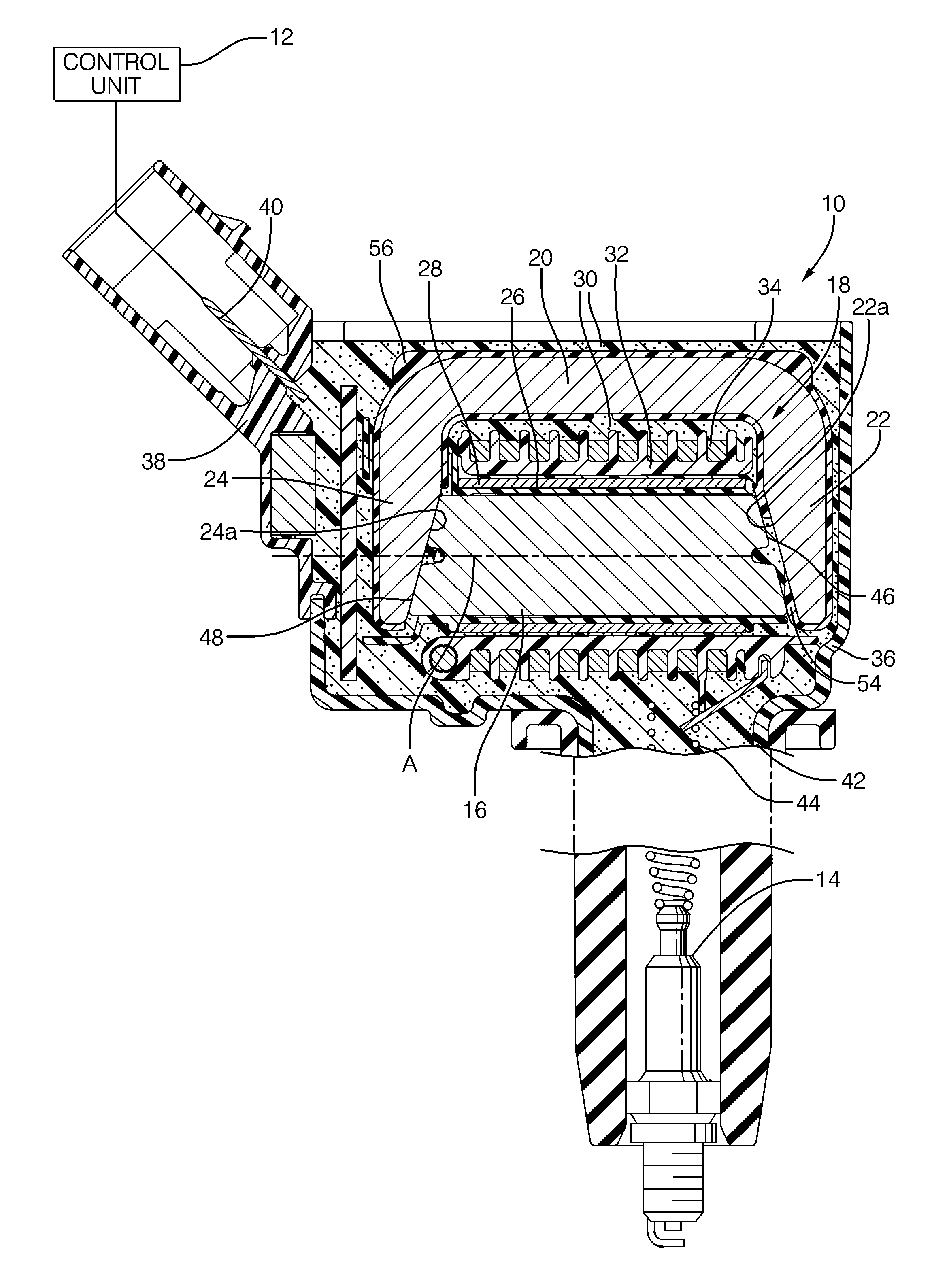
[0015]Referring now to the drawings wherein like reference numerals are used to identify identical components in the various views, FIG. 1 is a simplified cross-section view of an ignition coil 10. Ignition coil 10 may be controlled by a control unit 12 or the like. Ignition coil 10 is configured for connection to a spark plug 14 that is in threaded engagement with a spark plug opening (not shown) in an internal combustion engine (also not shown). Ignition coil 10 is configured to output a high-voltage (HV) output to spark plug 14, as shown. Generally, overall spark timing (dwell control) and the like is provided by control unit 12. One ignition coil 10 may be provided per spark plug 14.

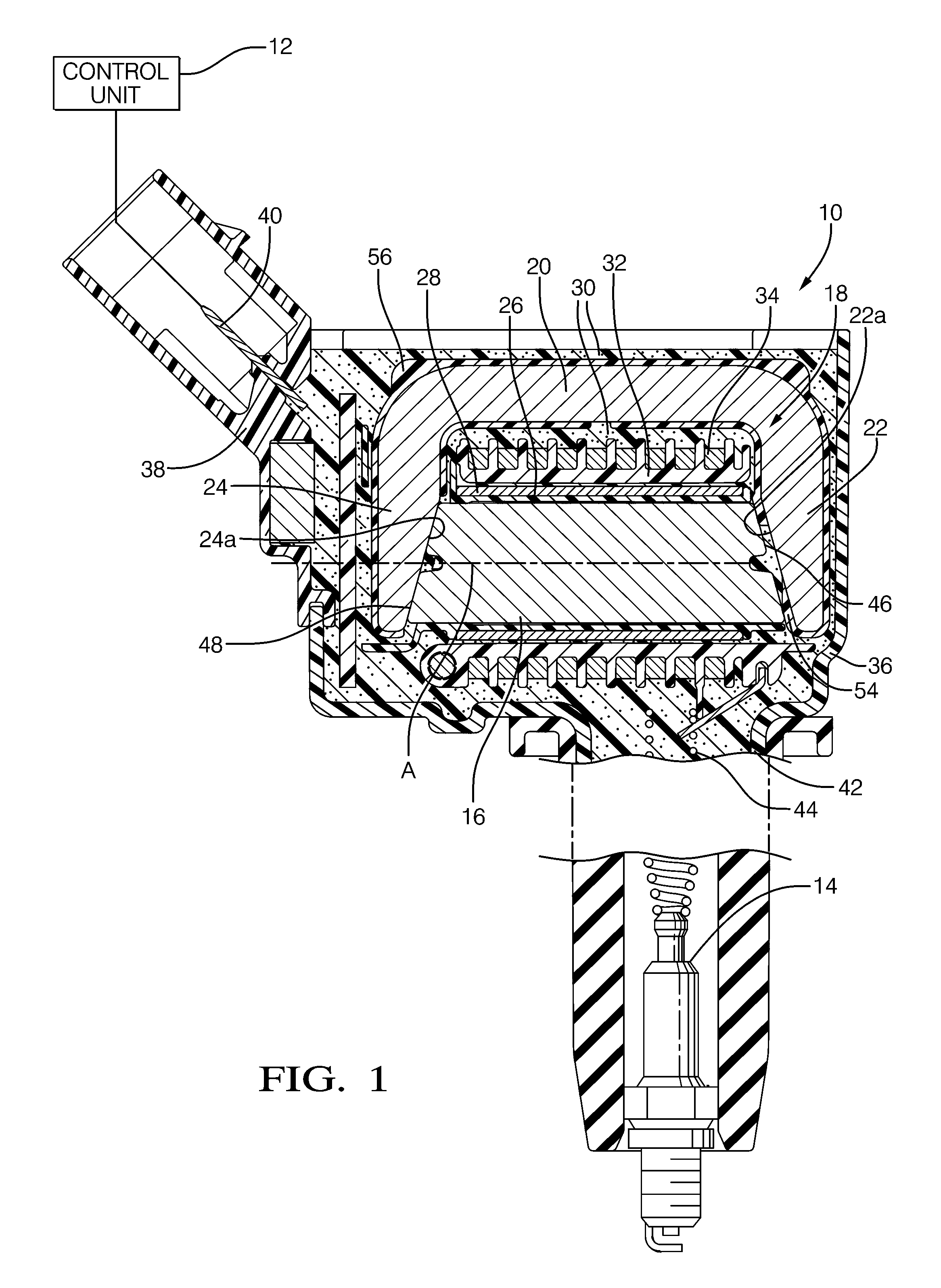
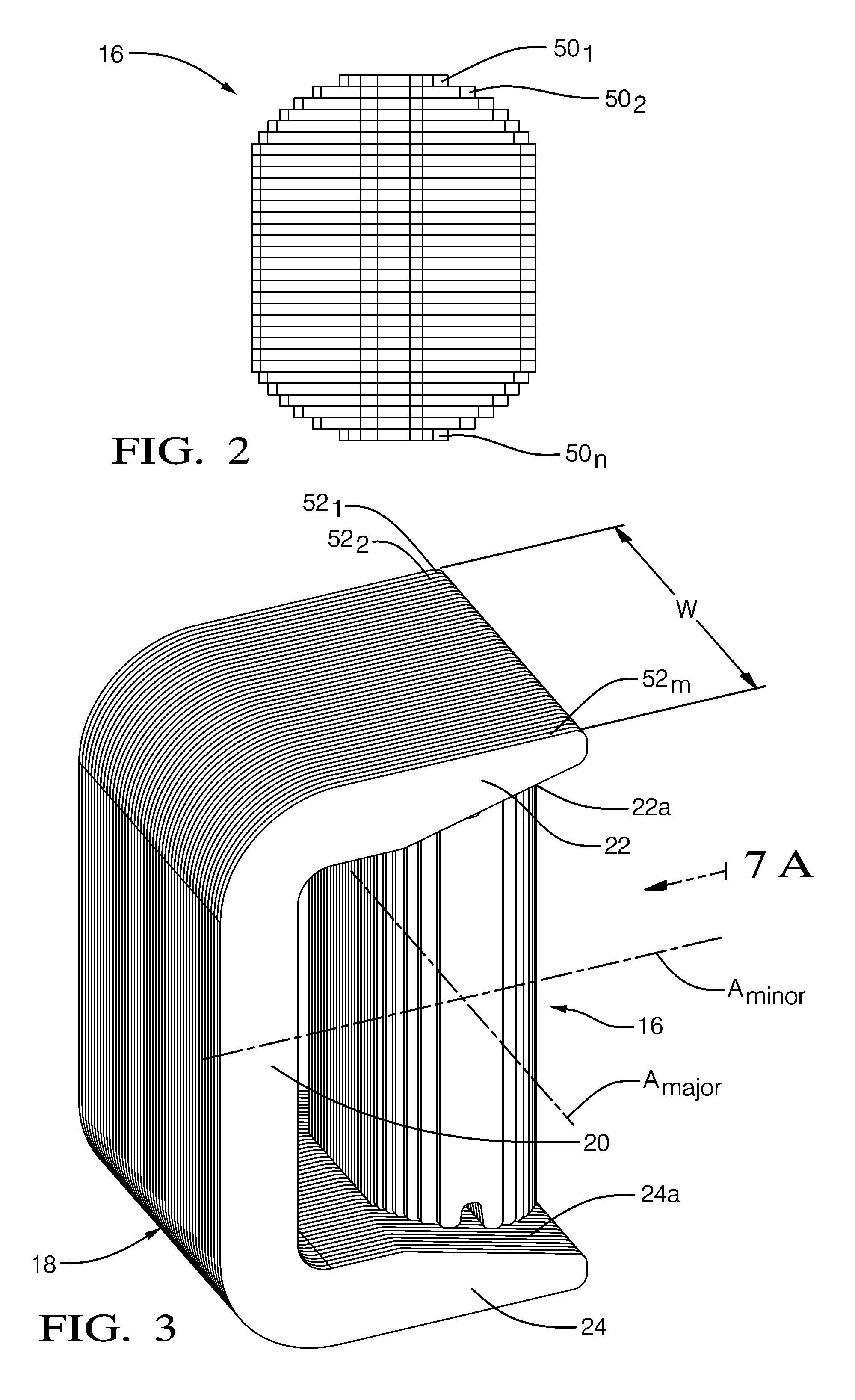
[0016]Ignition coil 10 may include a magnetically-permeable core 16, a magnetically-permeable structure 18 configured to provide a high permeance magnetic return path which has a base section 20 and a pair of legs 22 and 24, a primary winding spool 26, a primary winding 28, a quantity of encapsulant ...


PUM


Abstract

An ignition coil for an internal combustion engine includes a magnetically-permeable core extending along a core longitudinal axis, the core having a pair of end surfaces on axially-opposite ends thereof. The ignition coil also includes a primary winding disposed outward of the core, a secondary winding disposed outward of the primary winding, and a structure comprising magnetically-permeable steel laminations having a base and a pair of legs, the structure defining a magnetic return path. The core is disposed between the pair of legs such that the core longitudinal axis extends through the legs and the end surfaces face toward the legs and at least one of the end surfaces of the core is spaced apart from a respective one of the legs to define an air gap. The structure is over-molded with an over-molding material such that the over-molding material fills at least a portion of the air gap.

Description

TECHNICAL FIELD OF INVENTION[0001]The present invention relates to an ignition coil for developing a spark firing voltage that is applied to one or more spark plugs of an internal combustion engine.BACKGROUND OF INVENTION[0002]Ignition coils are known for use in connection with an internal combustion engine such as an automobile engine. Ignition coils typically include a primary winding, a secondary winding, and a magnetic circuit. The magnetic circuit conventionally may include a central core extending along an axis and located radially inward of the primary and secondary windings and magnetically coupled thereto. In one arrangement, a C-shaped high permeance structure is included to provide a high permeance magnetic return path. The high permeance structure may include a base section from which a pair of legs extends. The central core is placed between the legs such that the axis of the core extends through the legs of the high permeance structure and such that at least one end of...

Claims


Application Information

Patent Timeline
Patent Type & Authority Applications(United States)
IPC IPC(8): F02P1/00
CPCH01F27/022H01F38/12
Inventor SKINNER, ALBERT A.LEVERS, HARRY O.SCAFF, ANDRE V.
Owner DELPHI TECH IP LTD
Why Eureka
Try Eureka