Wheel rolling bearing unit

a technology of rolling bearings and bearings, which is applied in the direction of mechanical equipment, rotary machine parts, transportation and packaging, etc., can solve the problem that the required rigidity cannot be obtained securely in some cases

Inactive Publication Date: 2013-11-07
JTEKT CORP
View PDF1 Cites 5 Cited by
  • Summary
  • Abstract
  • Description
  • Claims
  • Application Information

AI Technical Summary

Problems solved by technology

Furthermore, although the diameter of the bearing unit on the outboard side (the outward side of the vehicle) having a flange surface on which a wheel is mounted has a higher degree of desi

Method used


Image

  • Wheel rolling bearing unit
  • Wheel rolling bearing unit
  • Wheel rolling bearing unit

Examples


first embodiment (fig.2)

First Embodiment (FIG. 2)

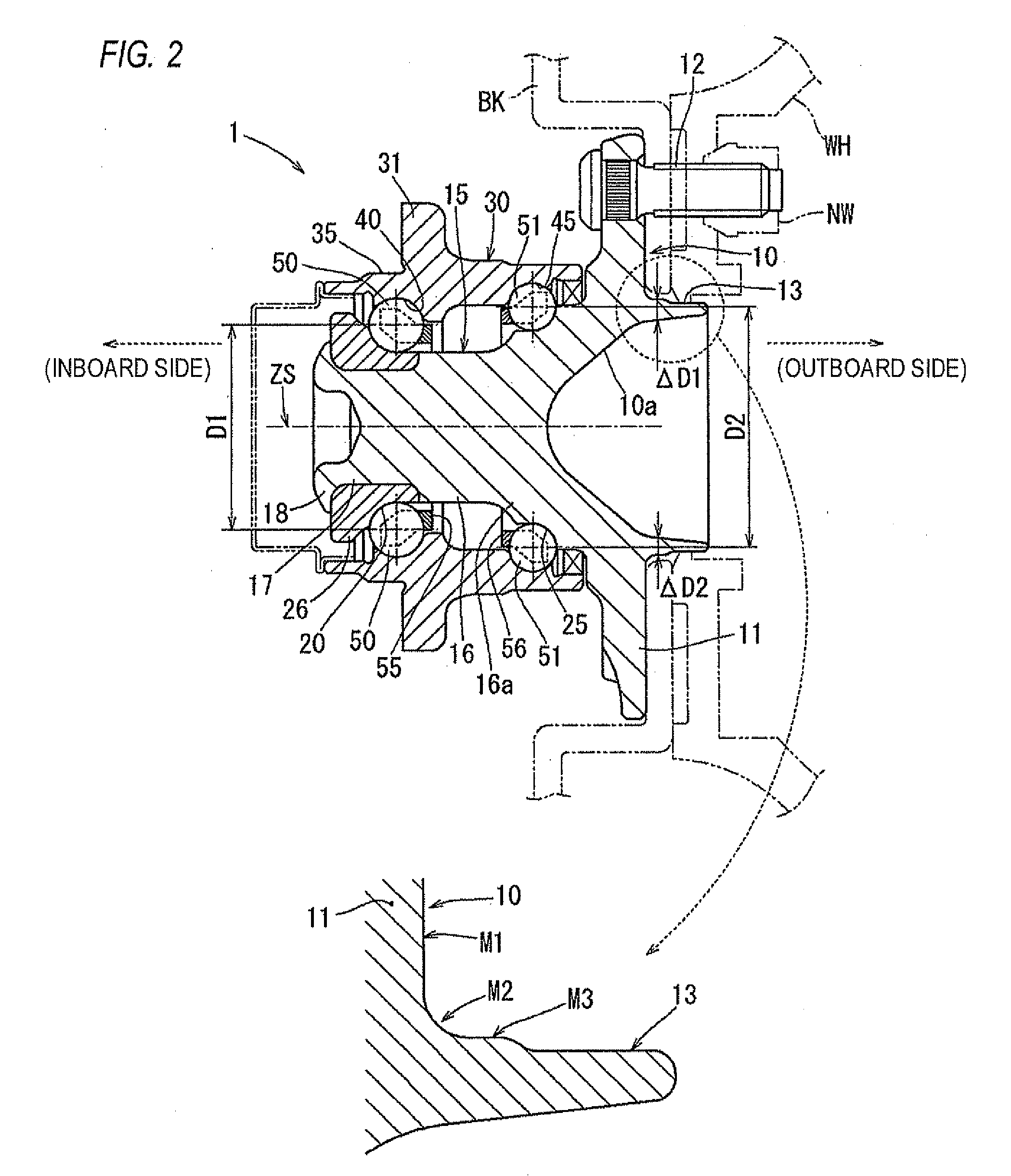
[0049]In a first embodiment, the surface roughness of an arc-shaped (in cross-section) boundary surface M2 at a boundary section where the outer peripheral surface M3 of the spigot joint section 13 is smoothly connected to the flange surface M1 is made finer (refer to FIG. 2).

[0050]As shown in FIG. 2, since the stress from the brake rotor BK and the wheel WH is concentrated in the boundary surface M2 (round chamfered section) of the spigot joint section 13, reduction in fatigue strength may occur. Hence, the surface roughness of the boundary surface M2 is made finer by turning or grinding.

[0051]For example, in the case of turning, the flange surface M1 and the outer peripheral surface M3 of the spigot joint section 13 are machined so that an arithmetic average roughness of Ra=6.3 [μm] is obtained; and in the case of machining the boundary surface M2, the machining is performed at a low feed rate so that Ra=2.5 [μm] is obtained.

[0052]As a result, reduction in...

second embodiment (

FIGS. 1(A) and 1(B))

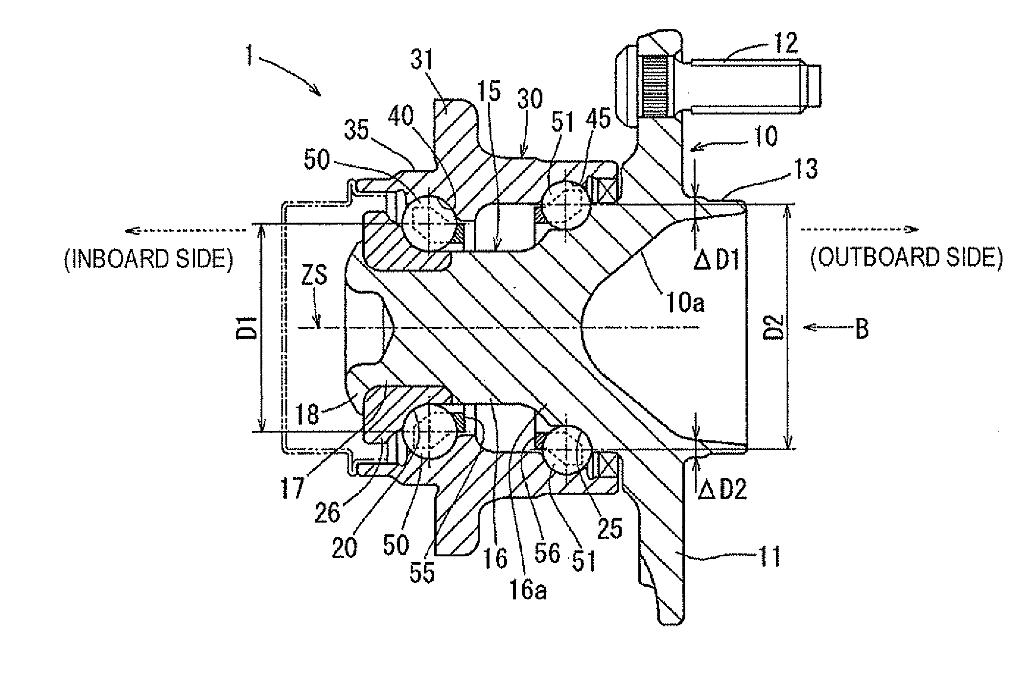
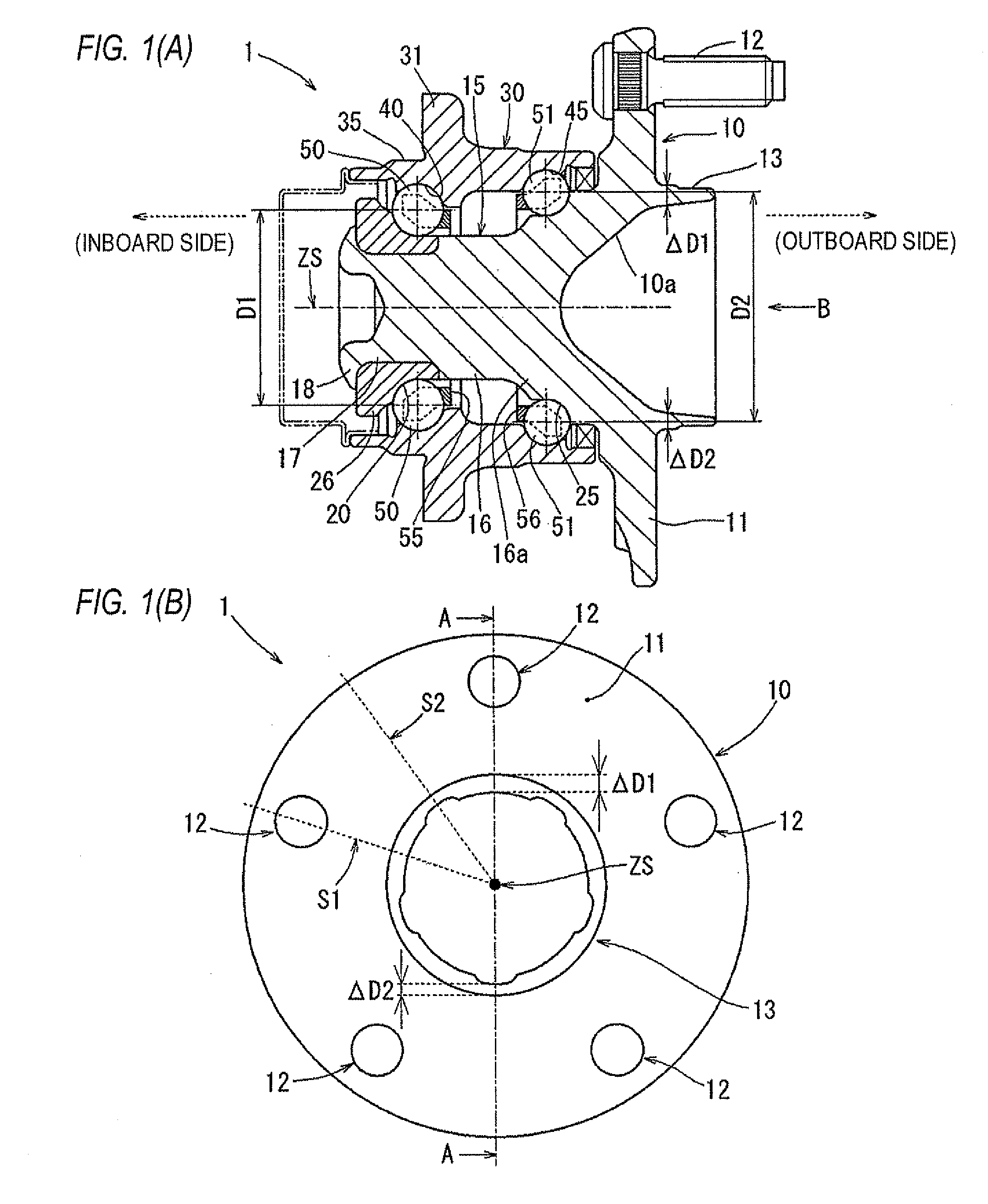
[0054]In a second embodiment, while attention is paid to the fact that the brake rotor BK and the wheel WH are secured to the flange section 11 of the hub spindle 10 using the plurality of hub bolts 12, the thickness at positions on the spigot joint section 13 not corresponding to the positions of the hub bolts 12 is made thinner partially.

[0055]As shown in FIG. 1(B), it is assumed that the radial thickness of the spigot joint section 13 around the intersection point of a non-bolt position straight line S2 (refer to FIG. 1(B)) serving as a straight line drawn in the radial direction from the rotation axis ZS toward each intermediate position between the hub bolts 12 adjacent to each other and the spigot joint section 13 is a non-bolt position thickness ΔD2.

[0056]In addition, it is assumed that the radial thickness of the spigot joint section 13 around the intersection point of a bolt position straight line S1 (refer to FIG. 1(B)) serving as a straight line drawn ...


PUM


Abstract

A wheel rolling bearing unit has a hub spindle having flange and shaft-shaped sections, an inner-ring raceway surface on the outer peripheral surface of the shaft-shaped section; an outer ring member disposed around the outer periphery of the shaft-shaped section, an outer-ring raceway surface on the inner peripheral surface thereof; and rolling elements between the inner-ring raceway and outer-ring raceway surfaces. The flange section is on one side of the spindle in a rotation axis direction thereof; on the flange surface, a cylindrical spigot joint section protruding on one side is coaxial with the spindle; the boundary section of the flange surface and the outer peripheral surface of the spigot joint section has an arc-shaped boundary surface to connect smoothly toward the flange surface. The surface roughness of the boundary surface is finer than that of the flange surface and the outer peripheral surface of the spigot joint section.

Description

TECHNICAL FIELD[0001]The present invention relates to a wheel rolling bearing unit to be used as a wheel bearing for vehicles or the like.BACKGROUND ART[0002]Recent vehicles or the like are requested to be lighter in weight (improvement in fuel efficiency) to comply with CO2 emission regulations and also requested to be higher in rigidity to improve safety and mobility; hence, wheel rolling bearing units are also requested to be lighter in weight and higher in rigidity.[0003]In a wheel rolling bearing unit to be used as a wheel bearing for vehicles or the like, the diameter thereof on the inboard side (the inward side of a vehicle) is determined to be relatively small in relation to suspension-related components (a knuckle, a carrier or the like) to which the bearing unit is connected (the diameter is determined so as to conform to the diameter depending on weight reduction or the like of the suspension-related components to which the bearing unit is connected). Furthermore, althoug...

Claims


Application Information

Patent Timeline
IPC IPC(8): B60B27/00
CPCB60B27/0005B60B23/04B60B23/10B60B25/20F16C33/581F16C2326/02B60B27/00B60B2900/111B60B2900/311F16C19/186B60B27/0094F16C2240/54Y02T10/86F16C2240/80F16C33/60
Inventor YOKOTA, TATSUYAOKUMURA, TSUYOSHISEO, NOBUYUKI
Owner JTEKT CORP
Why Eureka
Try Eureka