Remotely adjustable solid-state lamp

a technology of solid-state lamps and remote adjustment, which is applied in the direction of electric variable regulation, process and machine control, instruments, etc., can solve the problems of limiting the ability to control the intensity of individual luminaires, physical access to individual luminaire controls, and a combination of all. individual adjustment of the intensity of each luminaire can be disruptive, time-consuming, and costly

Active Publication Date: 2013-11-07
EXPRESS IMAGING SYST
View PDF5 Cites 126 Cited by
  • Summary
  • Abstract
  • Description
  • Claims
  • Application Information

AI Technical Summary

Problems solved by technology

A single electrical circuit is frequently used to provide power to multiple luminaires thereby limiting the ability to control the intensity of an individual luminaire on the electrical circuit, as a change in any electrical parameter (e.g., a reduction in voltage) will be reflected in ALL of the luminaires coupled to the electric circuit.
Additionally, luminaires are frequently mounted at elevations rendering physical access to controls on individual luminaires, impractical, difficult, dangerous, or a combination of all three.
Thus, individually adjusting the intensity of each luminaire can be disruptive, time-consuming, and costly.
However, the inherent energy inefficiency and relatively short operating life of incandescent lamps is both financially unsound, requiring dimmer control wiring between each luminaire and a dimmer switch, and ecologically wasteful, using inefficient, short-lived, incandescent lamps.
Other lamps, for example high efficiency lighting devices, such as metal halide lighting devices, typically cannot be dimmed effectively.
Although some metal halide ballasts are configured to permit dimming, such ballasts generally require extensive wiring and control systems to enable dimming.
Similar to the approach using a wall-mounted dimmer, connecting additional wiring to support use of a multiple-position switch adds hardware and labor costs to the lighting installation.
Additionally, installing filters to adjust the output intensity of the lighting device wastes energy by reducing the overall output of the lighting device and suffers from the drawbacks associated with having a person physically elevated to the lighting device to install the filters.

Method used


Image

  • Remotely adjustable solid-state lamp
  • Remotely adjustable solid-state lamp
  • Remotely adjustable solid-state lamp

Examples


Embodiment Construction

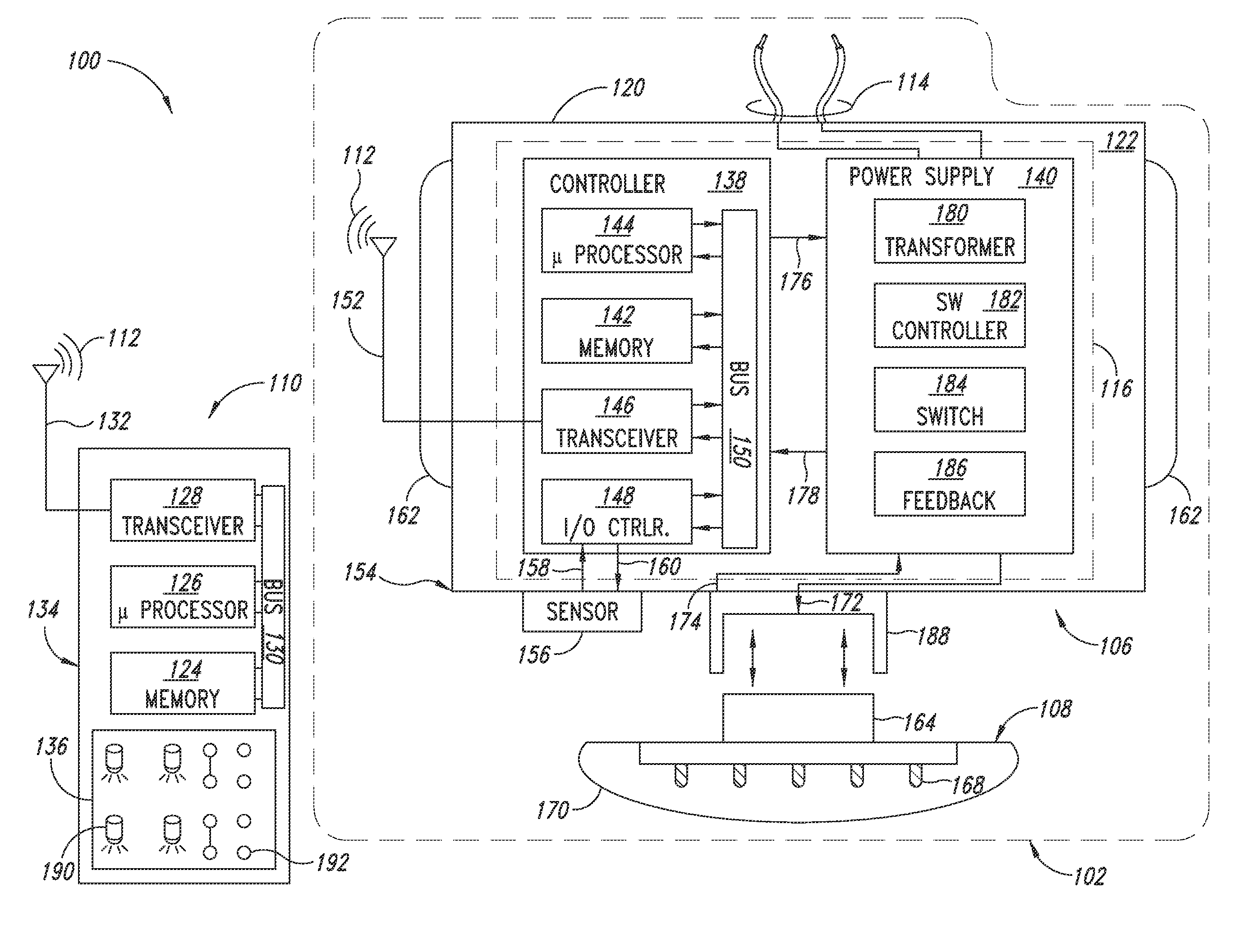
[0042]In the following description, certain specific details are set forth in order to provide a thorough understanding of various disclosed embodiments. However, one skilled in the relevant art will recognize that embodiments may be practiced without one or more of these specific details, or with other methods, components, materials, etc. In other instances, well-known structures associated with lighting systems, for example power converters, thermal management structures and subsystems, and / or solid state lights have not been described in detail to avoid unnecessarily obscuring descriptions of the embodiments.

[0043]Unless the context requires otherwise, throughout the specification and claims which follow, the word “comprise” and variations thereof, such as, “comprises” and “comprising” are to be construed in an open, inclusive sense, that is as “including, but not limited to.”

[0044]Reference throughout this specification to “one embodiment” or “an embodiment” means that a particu...


PUM


Abstract

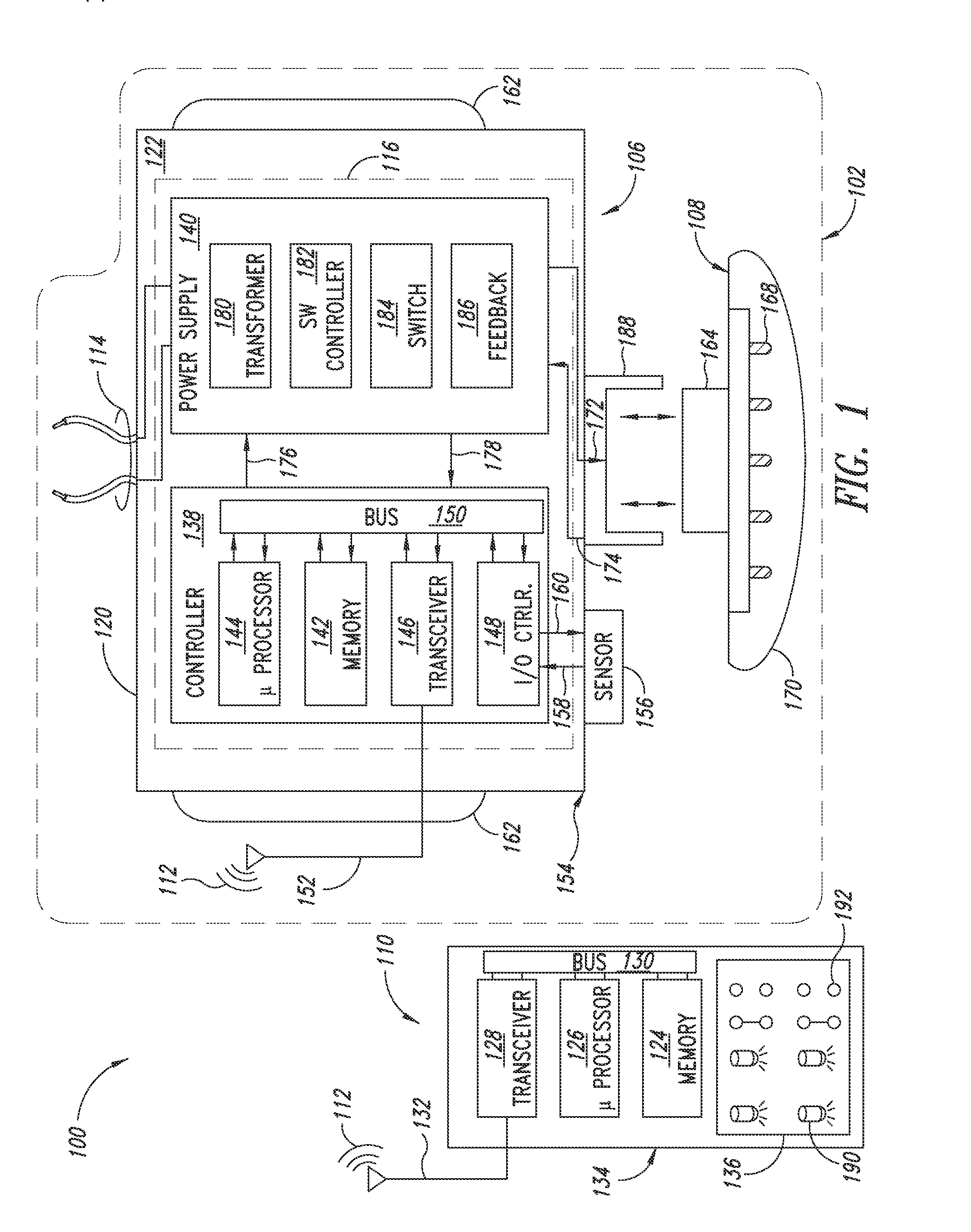
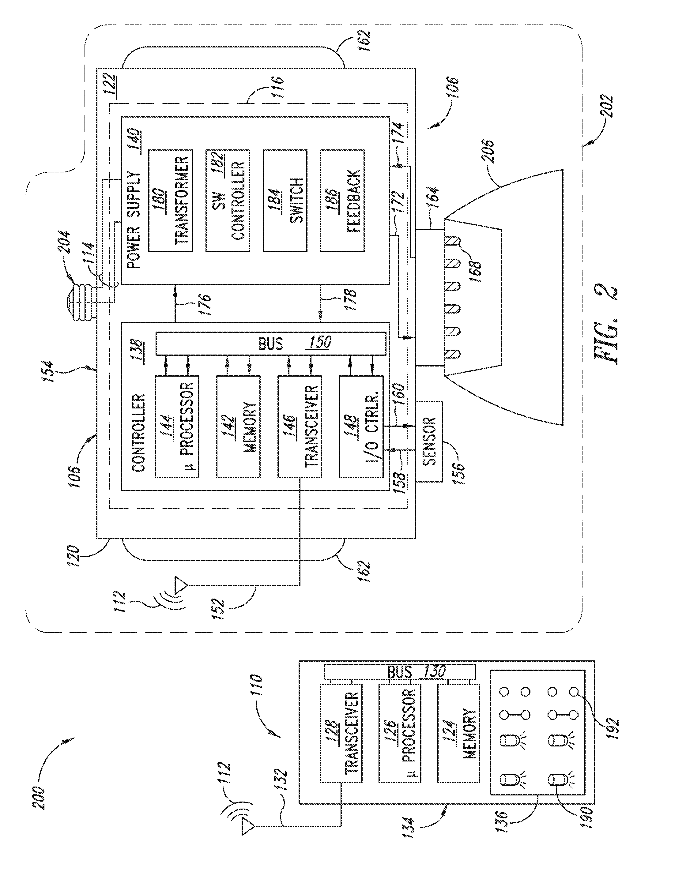
Disclosed herein is a remotely adjustable lighting system. The lighting system includes a luminaire including one or more solid-state light systems and a non-line-of-sight wireless transceiver. The output intensity of the solid-state light systems is adjustable. The non-line-of-sight transceiver in the luminaire can receive one or more non-line-of-sight wireless signals transmitted by a transceiver in a general purpose handheld computing device. Instructions and data including configuration and output intensity adjustments may be communicated between the general purpose handheld computing device and the luminaire via one or more non-line-of-sight wireless signals.

Description

BACKGROUND[0001]1. Technical Field[0002]This disclosure is generally related to solid-state lamps.[0003]2. Description of the Related Art[0004]Fixed intensity lighting has been in use for more than a century. While fixed intensity lighting is useful in many applications, some applications benefit from the ability to control lighting intensity, adjust lighting intensity or synchronize lighting intensity with one or more scheduled events. In one particular application, it may be desirable to adjust the intensity of only a portion of the lighting fixtures or luminaires used in a specific location such as an industrial facility, parking lot, or commercial establishment. Adjusting the intensity of only a portion of the luminaires within a given location enables the use of selective or scheduled lighting scheme. For example, luminaires above a continuously occupied (i.e., 24 / 7 / 365) work area may be maintained at maximum intensity at all times, while other luminaires above a periodically o...

Claims


Application Information

Patent Timeline
Patent Type & Authority Applications(United States)
IPC IPC(8): H05B37/02H05B44/00
CPCH05B37/0272H05B33/0863H05B45/20H05B47/19H05B47/105H05B47/11H05B47/16Y02B20/40
Inventor REED, WILLIAM G.DEGRAFF, DALE H.
Owner EXPRESS IMAGING SYST
Why Eureka
Try Eureka