
Reflector and lamp comprised thereof

a technology of reflectors and lamps, applied in the field of lamps, can solve the problems of insufficient heat dissipation, inability to replicate the intensity distribution of incandescent lamps in satisfactory manner or sufficient extent, and high unidirectional nature of led-based devices

Inactive Publication Date: 2013-11-07
GE LIGHTING SOLUTIONS LLC
View PDF25 Cites 15 Cited by
  • Summary
  • Abstract
  • Description
  • Claims
  • Application Information

AI Technical Summary

Benefits of technology

The patent text is about a new LED lamp that aims to encourage more people to switch from traditional incandescent lamps to more energy-efficient alternatives. The new LED lamp produces light with a consistent optical intensity distribution that mimics the light from traditional incandescent lamps. The new LED lamp also has a longer lifespan and higher efficiency compared to traditional lamps. Additionally, the new LED lamp dissipates heat effectively and efficiently without affecting the consistent distribution of light.

Problems solved by technology

LED-based devices do have one significant disadvantage in some applications; namely, LED-based devices are highly unidirectional by nature.
Thus, although superior with respect to certain performance aspects, the intensity distribution of many commercially available LED lamps designed to be suitable alternative and / or replacement for incandescent lamps cannot replicate the intensity distribution of incandescent lamps in satisfactory manner or to a sufficient extent.
Another challenge related to solid-state lighting technologies is the need to find a way to dissipate heat adequately.
Unfortunately, the heat sink, depending on the placement thereof, may block all or a portion of the light that the LED lamp emits, thus, may limit further the ability of the LED lamp to generate light with a more uniform optical intensity distribution.
Moreover, physical constraints on lamps such as regulatory limits that define maximum dimensions for all lamp components, including light sources, limit further an ability to dissipate heat sufficiently and efficiently for LED-based lamps

Method used


Image

  • Reflector and lamp comprised thereof
  • Reflector and lamp comprised thereof
  • Reflector and lamp comprised thereof

Examples


examples

[0052]FIGS. 10, 11, 12, and 13 illustrate various form factors and constructions for embodiments of reflectors this disclosure contemplates herein. Examples of reflector 600 and 700 of FIGS. 10 and 11 having a conical reflector shape. In FIG. 10, the reflector 600 has an upward conical shape that may result when the center point of the outer profile (e.g., outer profile 546 of FIG. 9) is offset, or moved downwardly, along the axis 604 relative to the inner profile (e.g., inner profile 548 of FIG. 9). The reflector 700 of FIG. 7 has a downward conical shape that may result when the center point of the outer profile (e.g., outer profile 546 of FIG. 9) is offset, or moved upwardly, along the axis 704 relative to the inner profile (e.g., inner profile 548 of FIG. 9). FIG. 12 illustrates another configuration for the reflector 800 in which the surface at the bottom 808 of the reflector 800 can form a conical shape with curved and / or curvilinear features.

[0053]FIG. 13 depicts an exploded ...


PUM

PropertyMeasurementUnit
latitudeaaaaaaaaaa
angleaaaaaaaaaa
angleaaaaaaaaaa

Abstract

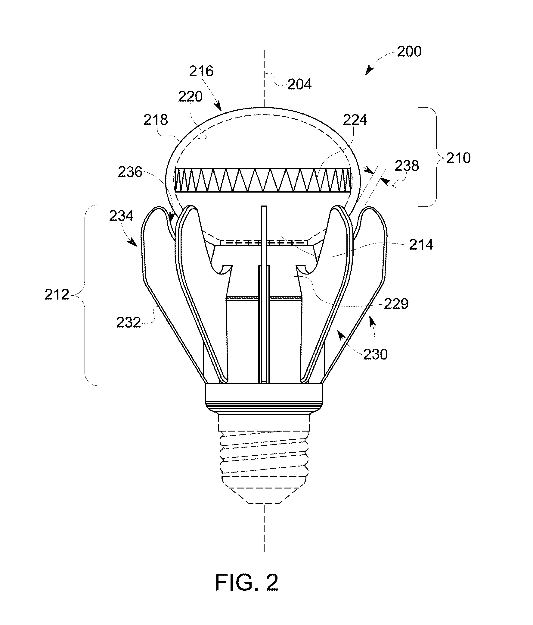
Embodiments of a reflector and a lamp that utilizes the reflector and light-emitting diode (LED) devices to generate an optical intensity distribution substantially similar to that of a conventional incandescent light bulb. The lamp can include a heat dissipating assembly with one or more heat dissipating elements disposed annularly about the envelope and spaced apart from the envelope in order to promote convective airflow. In one embodiment, the reflector operates as a total internal reflection (TIR) lens.

Description

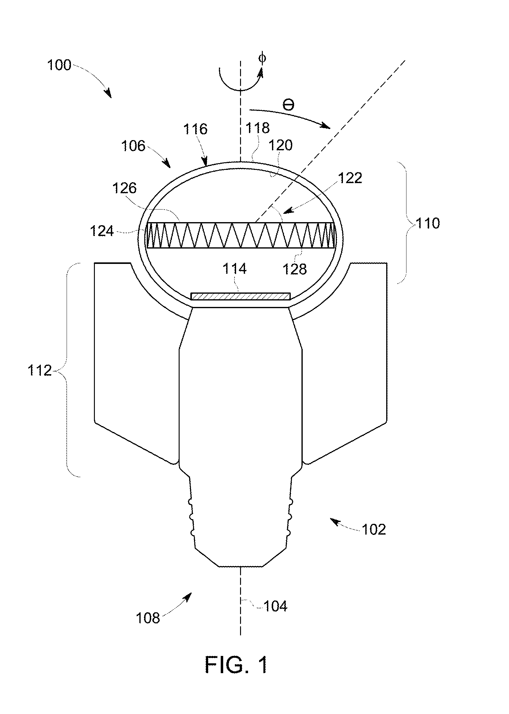
BACKGROUND[0001]1. Technical Field[0002]The subject matter of the present disclosure relates to lighting and lighting devices and, more particularly, to embodiments of a lamp that utilizes a directional light source and a reflector to generate an optical intensity distribution substantially similar to the optical intensity distribution of common incandescent lamps.[0003]2. Description of Related Art[0004]Incandescent lamps (e.g., integral incandescent light bulbs and halogen light bulbs) mate with a lamp socket via a threaded base connector (i.e. an “Edison base” in the context of an incandescent light bulb), a bayonet-type base connector (i.e. bayonet base in the context of an incandescent light bulb), or other standard base connector. These incandescent lamps are often in the form of a unitary package that includes components to operate the lamps from a source of standard electrical power (e.g., 110 V and / 02 220 V AC and / or 12 VDC and / or DC batteries). In the case of an incandesce...

Claims


Application Information

Patent Timeline
Patent Type & Authority Applications(United States)
IPC IPC(8): F21V7/04
CPCF21V7/048F21V3/02F21V5/02F21V7/0091F21V7/041F21V7/22F21V13/02F21V23/00F21V23/006F21Y2101/00F21Y2105/00F21V29/503F21V29/70F21K9/232F21K9/60F21Y2105/10F21Y2113/13F21Y2115/10F21Y2115/15F21V3/06F21V3/10F21V13/08F21V23/009F21V29/63F21V29/75F21V29/773F21V29/83F21V29/87F21K9/238F21V7/28G02B27/0972F21V29/507F21V29/60F21V29/67F21V29/74Y02B20/30
Inventor MAYER, MARK J.KUENZLER, GLENN HOWARDCHINNIAH, JEYACHANDRABOSEYODER, BENJAMIN LEE
Owner GE LIGHTING SOLUTIONS LLC
Learn More