Medical Implant And Manufacturing Method Thereof

a technology of medical implants and manufacturing methods, applied in the field of medical implants, can solve the problems of insufficient flexibility, inconvenient delivery, and increased complexity of devices, and achieve the effect of maintaining flexibility and safely delivering

Inactive Publication Date: 2013-11-07
OCCLUTECH HLDG
View PDF5 Cites 27 Cited by
  • Summary
  • Abstract
  • Description
  • Claims
  • Application Information

AI Technical Summary

Benefits of technology

[0016]Some embodiments of the invention provide for flexible positioning of a medical implant to varying anatomical sites in a body of a human or animal.
[0017]Some embodiments of the invention also provide for secure attachment of a medical implant in a patient's vascular system.
[0018]Some embodiments of the invention provide for a compact medical implant with maintained flexibility.
[0019]Some embodiments of the invention provide for a medical implant that can be safely delivered to a treatment site in a patient.

Problems solved by technology

The diameter and length of the PDA is determined by angiography in order to select the size of the device, where the latter dimension requirement is a particular issue due to the double disc design, which furthermore is increasing the complexity of the device and the delivery thereof.
A problem with the device is lack of flexibility and compactness of the device.
A problem with prior art is to achieve sufficient flexibility while maintaining a compact device.
A problem with prior art is to achieve a secure attachment of the device in the body while maintaining ease of delivery.
Also, a problem with prior art is that delivery of the device via the aorta having a high pressurized blood environment may give rise to several undesired conditions.
Debris, e.g. from arteriosclerotic deposits scraped loose by the device under delivery, for instance at ostia of branch vessels, may cause embolic complications.
Embolic material could thus be transported to vital organs, e.g. to the brain via the subclavian vessels, and cause blood clots, leading to stroke.
The above problems may have dire consequences for the patient and the health care system.
Patient risk is increased.

Method used


Image

  • Medical Implant And Manufacturing Method Thereof
  • Medical Implant And Manufacturing Method Thereof
  • Medical Implant And Manufacturing Method Thereof

Examples


Embodiment Construction

[0028]Specific embodiments of the invention will now be described with reference to the accompanying drawings. This invention may, however, be embodied in many different forms and should not be construed as limited to the embodiments set forth herein; rather, these embodiments are provided so that this disclosure will be thorough and complete, and will fully convey the scope of the invention to those skilled in the art. The terminology used in the detailed description of the embodiments illustrated in the accompanying drawings is not intended to be limiting of the invention. In the drawings, like numbers refer to like elements.

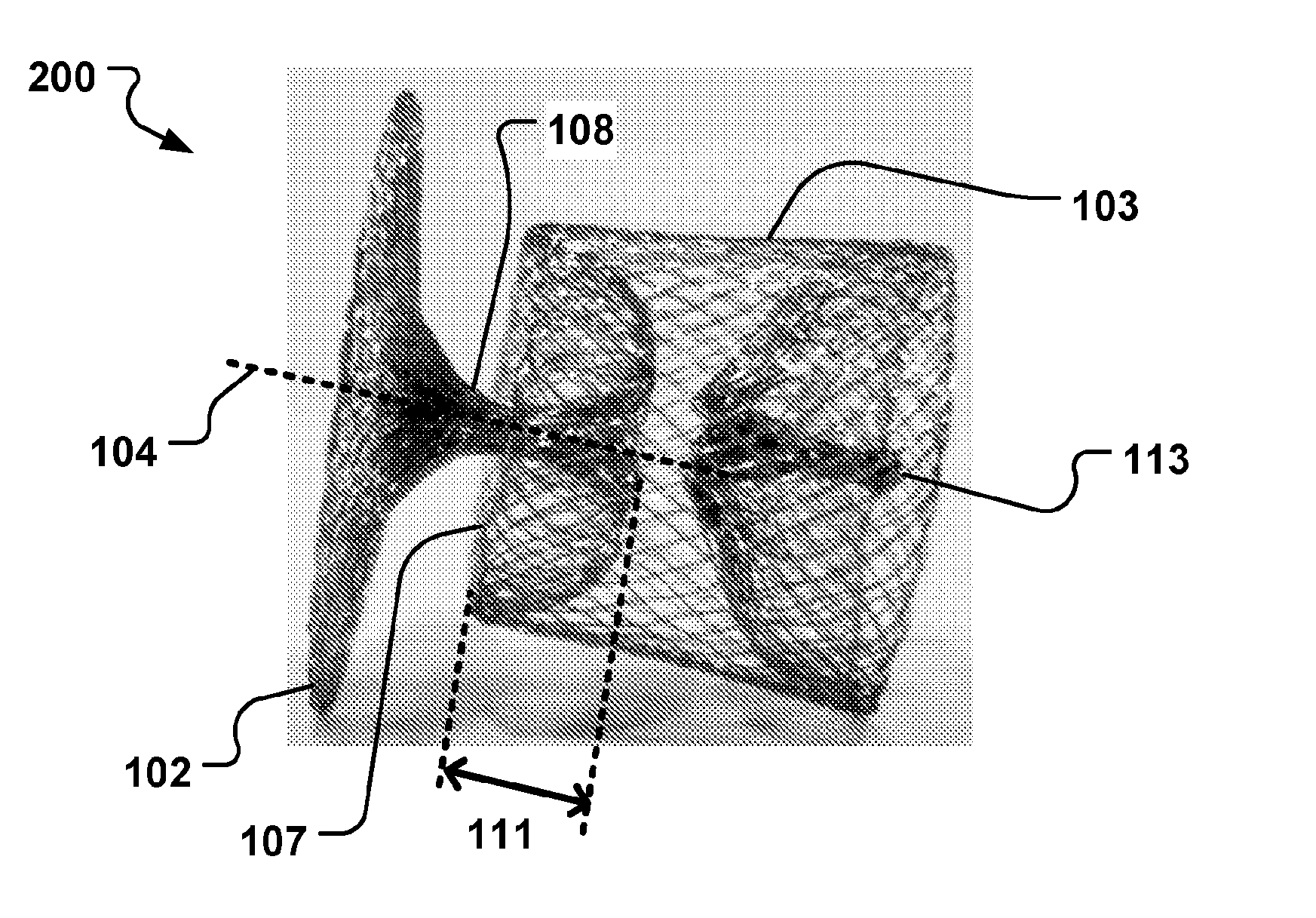
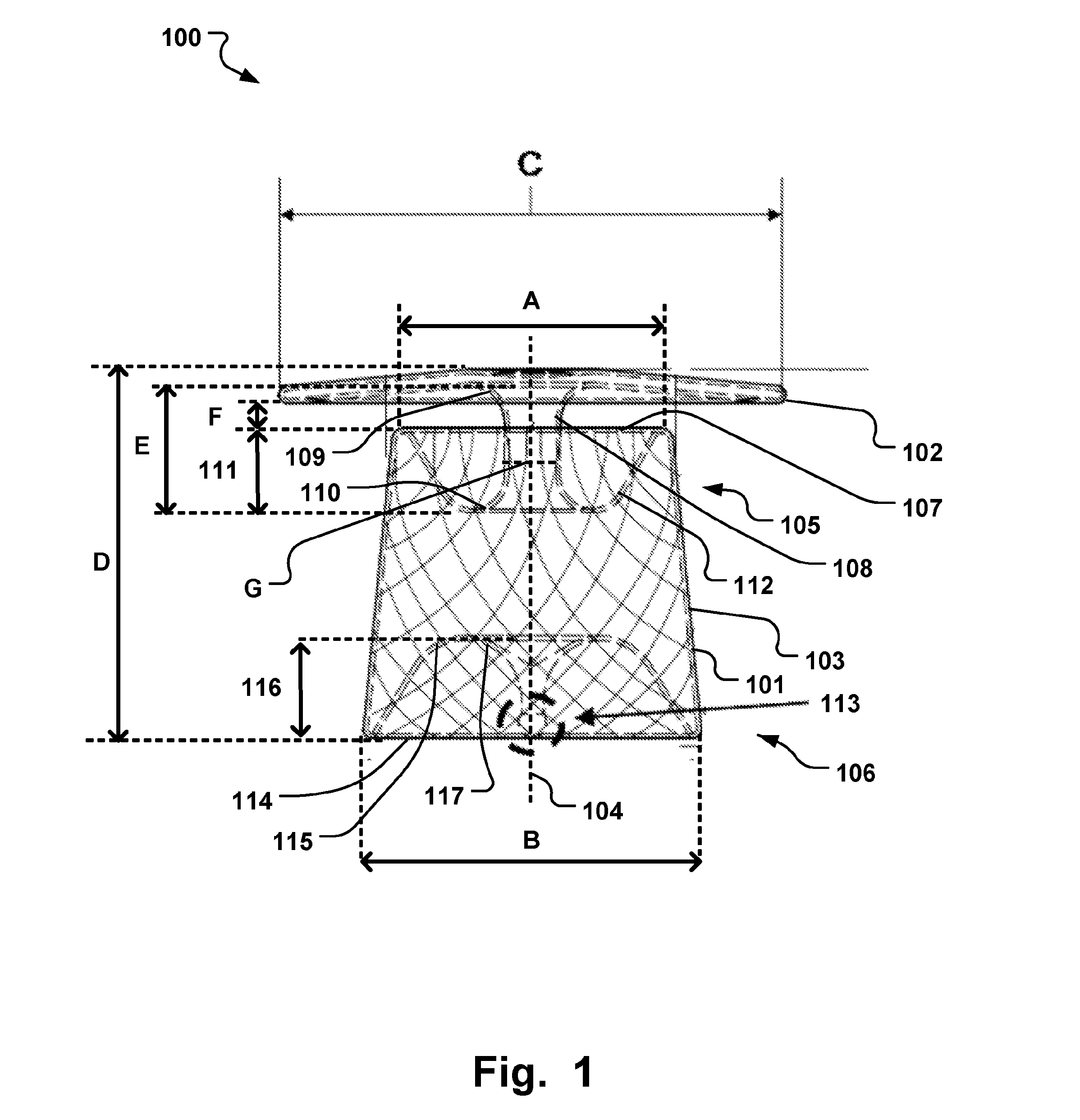
[0029]The following description focuses on an embodiment of the present invention applicable to a PDA plug. However, it will be appreciated that the invention is not limited to this application but may be applied to many other medical implantable devices, including for example filters, stents, Left Atrial Appendage (LAA) occluders, aneurysm treatment devices, ...


PUM

PropertyMeasurementUnit
diameteraaaaaaaaaa
lengthaaaaaaaaaa
shapeaaaaaaaaaa

Abstract

A medical implantable occlusion Device (100) is disclosed comprising a braiding of at least one thread, an expanded diameter portion (102), and a tubular member (103) having a distal endpoint closest to the expanded diameter portion having a distal rim (107). The braiding comprises a stem (108) having a first end connected to the expanded diameter portion and a second end connected to the distal region, where the stem in a relaxed state is partly sunk into the tubular member beneath the distal rim (107), wherein the proximal region comprises a connecting member (113), wherein ends of the at least one thread are fixed to the connecting member, the expanded diameter portion comprises returning loops of the at least one thread whereby opposite ends of the at least one thread forming the expanded diameter portion are fixed to the connecting member.

Description

FIELD OF THE INVENTION[0001]This invention pertains in general to the field of medical implants, as well as methods for manufacturing such implants. More particularly the invention relates to an intraluminally deliverable occlusion device for selective occlusion of a target site in a body lumen, such as the body's circulatory system.BACKGROUND OF THE INVENTION[0002]Various intravascular deliverable devices are used for treating specific conditions via access through body lumina, such as patients circulatory system. The target site may for instance be an atrial or ventricular septum having a defective opening to be occluded, such as devices for treating septal defects and the like. In certain circumstances, it may be necessary to occlude a patient's lumen, vessel, chamber, channel, hole, or cavity such as to stop blood flow there through. One such condition known in the art is a patent ductus arteriosus (PDA), which is essentially a condition wherein two blood vessels, most commonly ...

Claims


Application Information

Patent Timeline
Patent Type & Authority Applications(United States)
IPC IPC(8): A61B17/12
CPCA61B17/12172A61B17/0057A61B17/12109A61B2017/00526A61B2017/00575A61B2017/00592A61B2017/00606A61B2017/00628A61B2017/00867Y10T29/49826
Inventor OTTMA, RUDIGER
Owner OCCLUTECH HLDG
Why Eureka
Try Eureka