
Retarding system

Active Publication Date: 2013-11-14
CATERPILLAR INC
View PDF6 Cites 8 Cited by
  • Summary
  • Abstract
  • Description
  • Claims
  • Application Information

AI Technical Summary

Benefits of technology

This patent is about a machine that has a power source, a brake mechanism, and an engine retarder. The machine can determine if the operator doesn't need the machine to accelerate, and will activate the engine retarder at the same time as the brakes. The engine retarder can control a valve that increases the resistance of the power source. This allows for smoother braking and control of the machine.

Problems solved by technology

The natural resistance of the engine may dissipate some of the transferred power, thereby slowing the machine.
Moreover, during an “exhaust braking” operation, power may be dissipated by, for example, increasing backpressure in an exhaust manifold of the engine.
However, because such machines typically require the use of a separate pedal or other like operator interface device to activate and control such engine or exhaust braking, it can be difficult for machine operators to utilize engine or exhaust braking, in conjunction with the service brakes of the machine, in situations where such augmented machine braking is desired.
Although the braking system of the '408 patent may assist in controlling the travel speed of a vehicle, it may be inadequate for some situations.
In particular, because the compression brakes of the '408 patent are activated solely in response to brake pedal position, the responsiveness and controllability of the system described by the '408 patent may not be acceptable in, for example, emergency braking and / or extended braking operations.

Method used


Image

  • Retarding system
  • Retarding system
  • Retarding system

Examples


Embodiment Construction

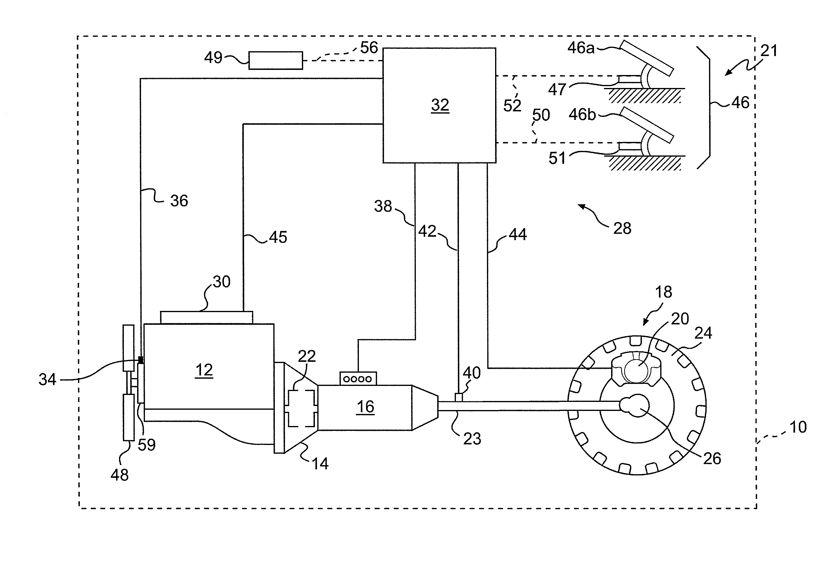
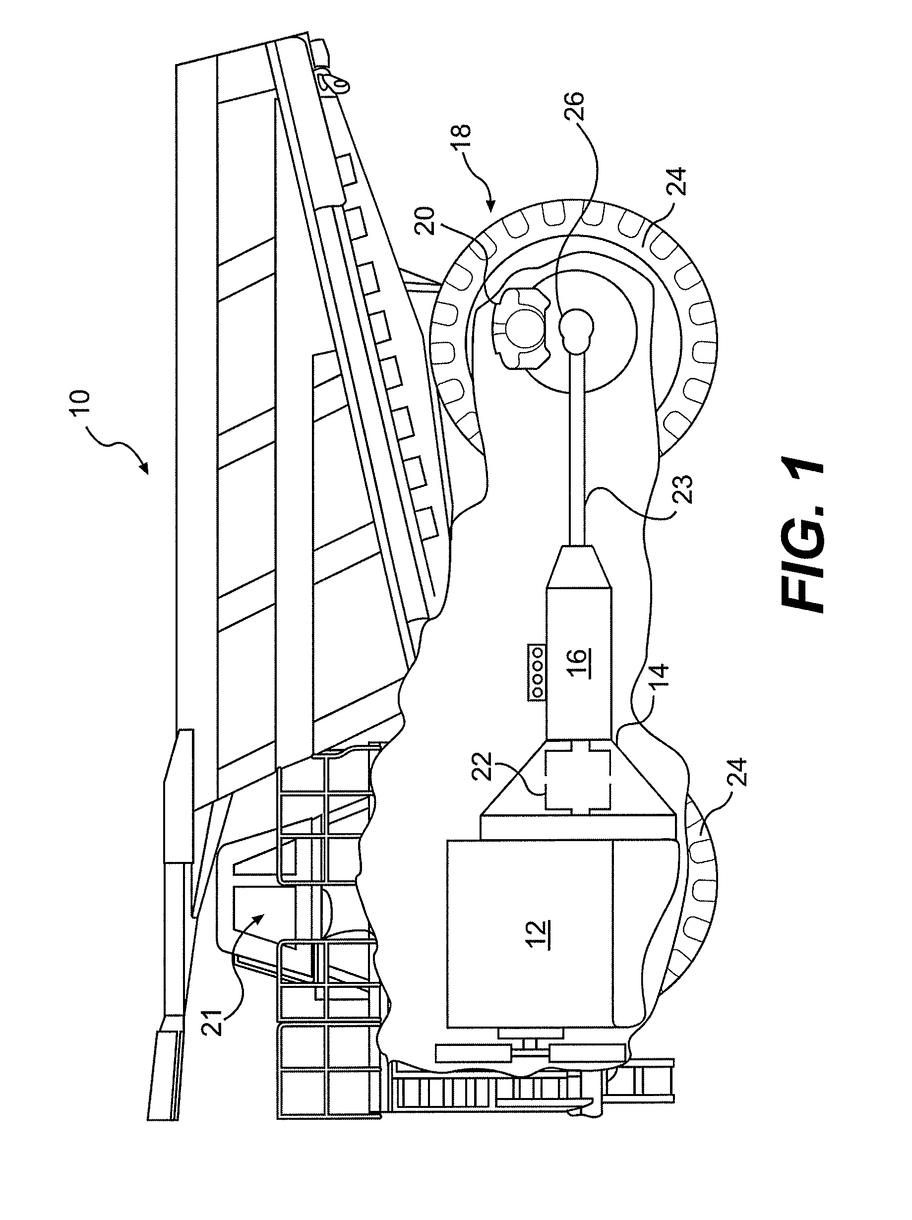
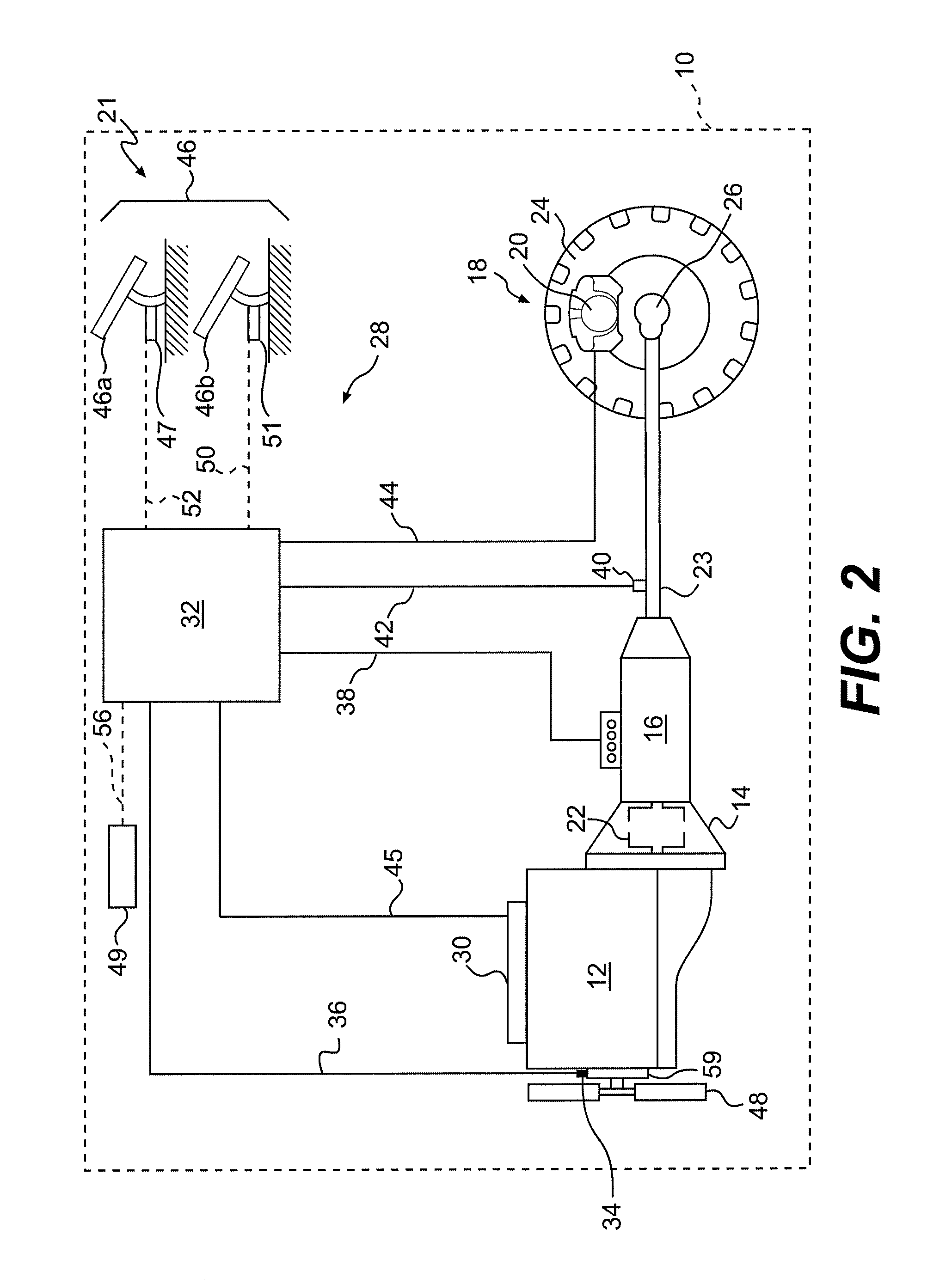
[0017]FIG. 1 illustrates an exemplary machine 10. The machine 10 may embody a mobile machine that performs some type of operation associated with an industry such as mining, construction, farming, transportation, or any other industry known in the art. For example, the machine 10 may be an earth moving machine such as an off-highway haul truck, a wheel loader, a motor grader, or any other suitable earth moving machine. The machine 10 may alternatively embody an on-highway vocational truck, a passenger vehicle, or any other operation-performing machine. The machine 10 may include, among other things, a power source 12, a torque converter 14, and a transmission 16. The machine 10 may also include a traction device 18 operably connected to the transmission 16, a brake mechanism 20 associated with the traction device 18, and an operator station 21.

[0018]The power source 12 may be configured to produce a power output and may include an internal combustion engine. For example, the power s...


PUM


Abstract

A machine includes a power source, an engine retarder associated with the power source, and a traction device receiving power from the power source and configured to propel the machine. The machine also includes a brake mechanism associated with the traction device, and a controller in communication with the engine retarder and the brake mechanism. The controller is configured to activate the engine retarder, substantially simultaneously with the brake mechanism, based on a brake pressure associated with the brake mechanism.

Description

TECHNICAL FIELD[0001]The present disclosure relates generally to a retarding system and, more particularly, to a retarding system that is responsive to fluid pressure.BACKGROUND[0002]Machines, including on and off-highway haul and vocational trucks, wheel loaders, motor graders, and other types of heavy machinery generally include a multi-speed, bidirectional, automatic transmission drivingly coupled to an engine by way of a hydraulic torque converter. The hydraulic torque converter multiplies and / or absorbs torque fluctuations transmitted from the engine to the transmission by allowing slippage between an output shaft of the engine and an input shaft of the transmission. Such machines also include one or more braking mechanisms, such as service brakes associated with the wheels of the machine, to controllably decelerate the machine when braking is required.[0003]Since the engine output and transmission input shafts are mechanically coupled, the engine can be used to assist the serv...

Claims


Application Information

Patent Timeline
IPC IPC(8): F02D13/04
CPCF02D13/04
Inventor HOLT, BRADFORD JAYGRILL, THOMAS LYNNANDERSON, STEVEN KOHL
Owner CATERPILLAR INC
Features
  • Generate Ideas
  • Intellectual Property
  • Life Sciences
  • Materials
  • Tech Scout
  • Unparalleled Data Quality
  • Higher Quality Content
  • 60% Fewer Hallucinations
Learn More