
Wind generating device

a wind power generation and wind power technology, applied in the direction of electric generator control, machines/engines, mechanical equipment, etc., can solve the problems of increasing the weight of the wind generating set itself, manufacturing various components, and installing the whole machine, so as to reduce the difficulty of developing a super high-power wind generating set, the overall mechanical stability of the wind power generation device is improved, and the stability of the tower column is enhanced.

Active Publication Date: 2013-11-14
JLANGSU DAODA OFFSHORE WIND CONSTR TECH CO LTD
View PDF3 Cites 12 Cited by
  • Summary
  • Abstract
  • Description
  • Claims
  • Application Information

AI Technical Summary

Benefits of technology

This patent describes a wind power generation device that connects multiple high-power wind generating sets to increase power output. The device also reduces interference between the blades of the wind generating sets, improves stability, and increases overall mechanical stability while achieving a high power output. The technical effects of this patent include reducing the difficulty in developing a super high-power wind generating set and improving the stability of the entire wind power generation device.

Problems solved by technology

However, as the power further increases, the diameter and weight of the blade continuously increase accordingly, and the weight of the wind generating set itself will also increase considerably; as a result, the difficulties in manufacturing various components and in installing the whole machine will increase significantly, thus restricting the potential of further enlarging the wind generating set.
However, since the plurality of wind wheels co-drives one generator to produce electricity, the requirement on the capacity of the generator is relatively high; moreover, a generator having a high capacity has undoubtedly increased the size of the generator, which is adverse to the overall arrangement and installation of cabin.
Therefore, during the operation of the plurality of wind wheels, identical torques will be induced on the frame; accordingly, the mechanical stability of the frame is low and the safety and reliability are poor.

Method used


Image

  • Wind generating device
  • Wind generating device
  • Wind generating device

Examples


Embodiment Construction

[0027]To make the objects, technical solutions and advantages of the present invention more apparent, the present invention will be further described in detail with reference to the accompanying drawings and in connection with particular embodiments hereinafter.

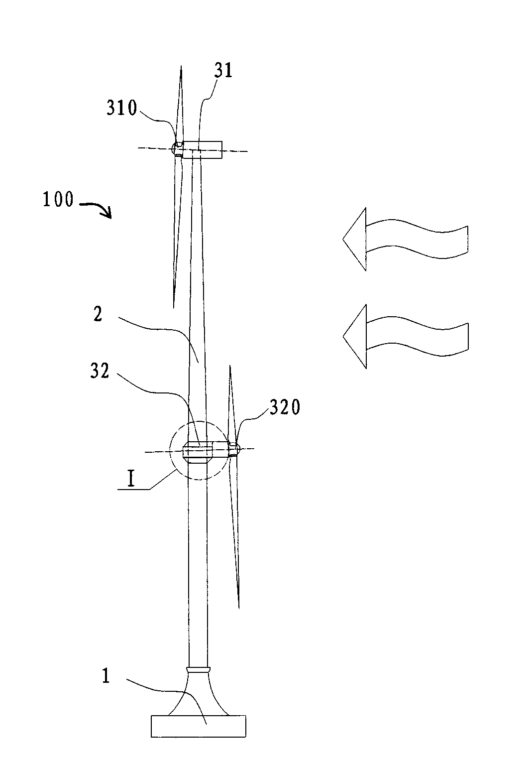
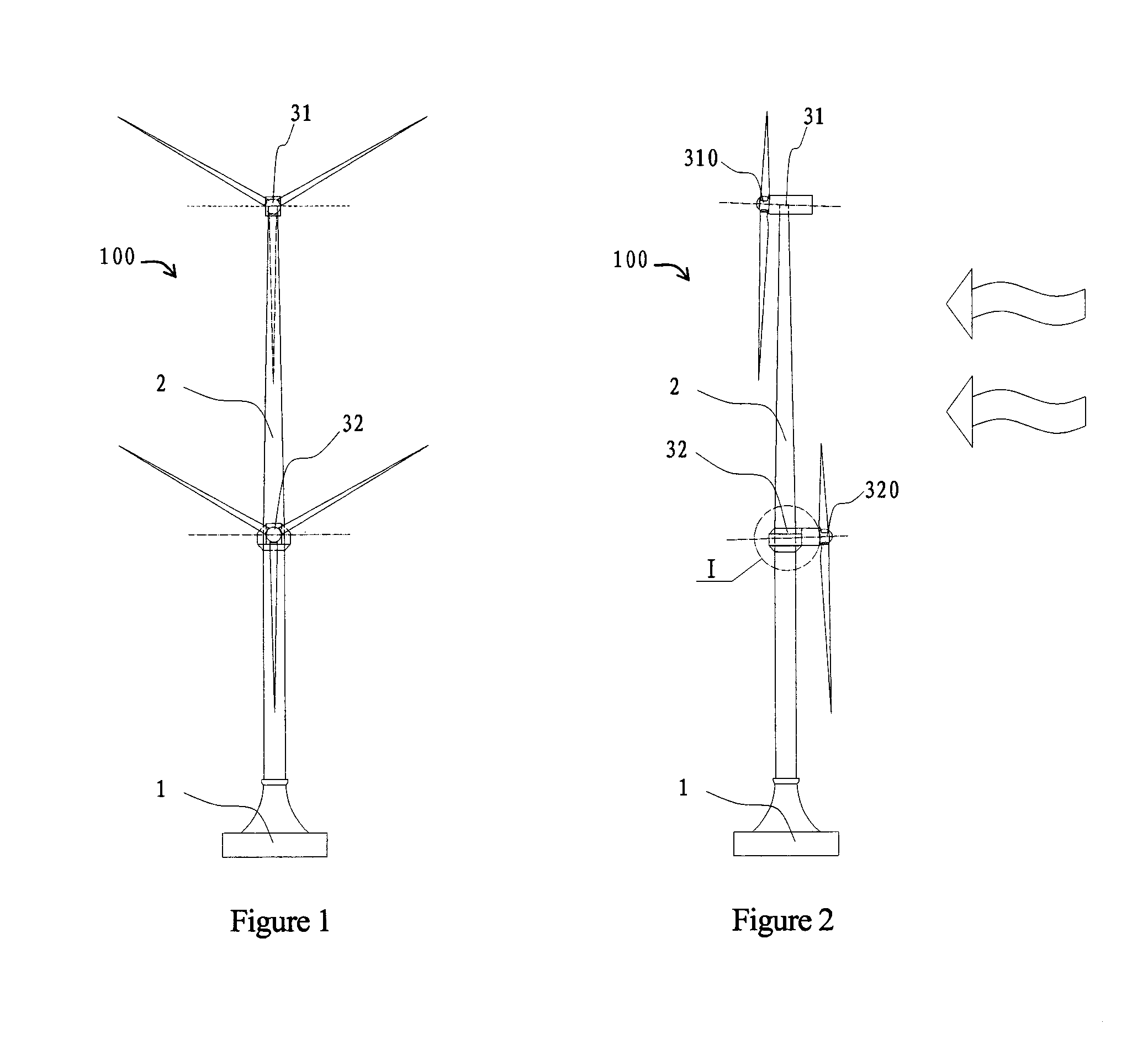
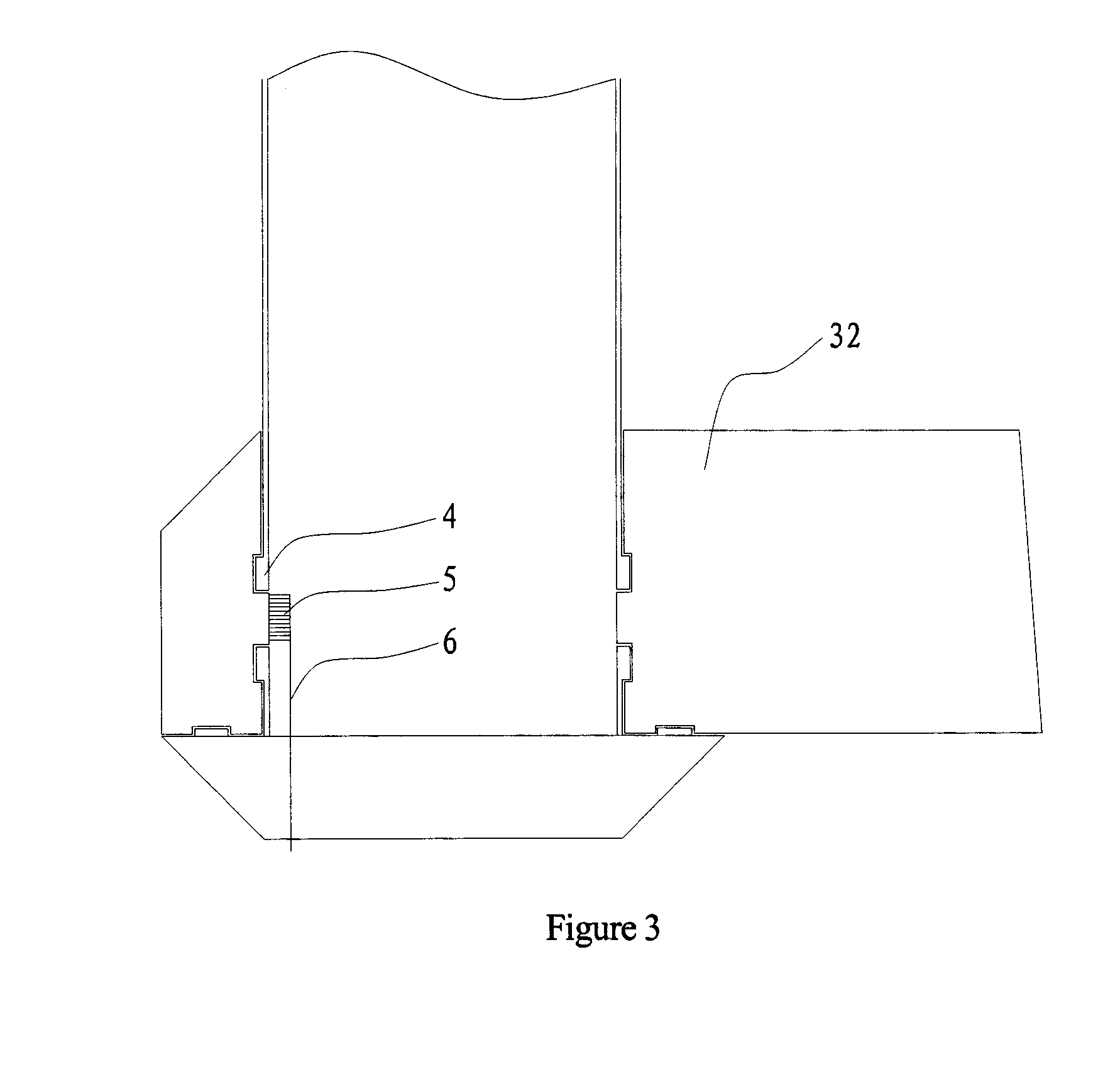
[0028]FIG. 1 is a structural schematic view of a wind power generation device according to an embodiment of the present invention. FIG. 2 is a side schematic view of the wind power generation device shown in FIG. 1. As shown in FIGS. 1 and 2, the wind power generating device 100 of the present invention comprises a cylindrical foundation 1, a tower column 2 installed on the cylindrical foundation 1 and a first wind generating set 31 and a second wind generating set 32 installed on the tower column 2.

[0029]The cylindrical foundation 1 can be a circular or polygonal complex cylindrical foundation with large dimension, or a combined structure of a plurality of complex cylindrical foundations. The cylindrical foundation 1 is at l...


PUM


Abstract

The present invention discloses a wind power generating device, comprising a tower column and a first wind generating set. The first wind generating set is installed at a position on the tower column near the top, and the first wind generating set generates a first torque on the tower column during rotation for power generating. At least one second wind generating set is installed at a position on the tower column below the top, the second wind generating set generates a second torque on the tower column during rotation for power generating, and the second torque at least partially counteracts with the first torque. With the wind power generating device of the present invention, a high power wind power generation is achieved and the wind power generating device operates stably.

Description

FIELD OF THE INVENTION[0001]The present invention relates to the technical field of wind power generation, and in particular to a wind power generating device.BACKGROUND[0002]With the continuous maturing of wind power generating technology and the continuous reduction of wind power generation cost, wind power generation has become one of the main sources of electric energy consumption. Wind power generation produces electric energy mainly by means of a wind generating set under the effect of wind. Wind power generation is an economical renewable energy which is easy to realize a large scale commercialization; besides, it pertains to a green and clean energy. With wind power generation, not only the abundant natural wind energy resource can be utilized to benefit human kind, but also the consumption of mineral fuels such as coal and oil can be reduced, thus alleviating the pressure of extreme energy shortage. In addition, the influence of environmental pollution such as dust, acid ra...

Claims


Application Information

Patent Timeline
Patent Type & Authority Applications(United States)
IPC IPC(8): F03D9/00
CPCF03D9/002F03D1/02F05B2240/2213F05B2260/96F03D9/25F03D80/70Y02E10/72
Inventor LI, AIDONGDING, HONGYANHUANG, XUANXU
Owner JLANGSU DAODA OFFSHORE WIND CONSTR TECH CO LTD
Learn More