
Constant Voltage Dimmable LED Driver

a technology of dimmable led drivers and constant voltage, which is applied in the direction of electroluminescent light sources, electric lighting sources, and use of semiconductors. it can solve the problems of significant deviation, abrupt shutoff or unstable, and fundamentally incompatible with conventional dimmers, and achieve the effect of quick creation of such dimmable led drivers

Inactive Publication Date: 2013-11-14
LIU GANG GARY
View PDF6 Cites 26 Cited by
  • Summary
  • Abstract
  • Description
  • Claims
  • Application Information

AI Technical Summary

Benefits of technology

The patent describes a method to create a stable and dimmable LED driver by using an AC-DC converter. The method includes a bleeper to provide minimum holding current for the dimmer, which can have small variations in its performance. This method enables the creation of a constant voltage type of dimmable LED driver by adding a few components to the design of a conventional AC-DC converter without or with very little modifications. The technical effect of this patent is the creation of a versatile and efficient solution for controlling LED lights that can be dimmed over a wide range of inputs.

Problems solved by technology

However, they are fundamentally incompatible with conventional dimmers, such as TRIAC dimmers, that are designed primarily for incandescent lamps.
Therefore, when a dimmer is used to reduce the voltage supplied to a conventional AC-DC converter, the converter still tries to maintain the same output voltage and will not dim the light, until the input voltage is so low that the converter cannot work anymore, it will abruptly shut off or become unstable.
However, all these designs require significant deviations from the design of conventional AC-DC converters and some are so complex as to require the use of microprocessors.
Therefore, these designs cannot leverage the well developed and perfected designs of conventional AC-DC converters.
As a result, the currently commercially available dimmable LED drivers are usually much more expensive than conventional AC-DC converters of the same wattage.

Method used


Image

  • Constant Voltage Dimmable LED Driver
  • Constant Voltage Dimmable LED Driver
  • Constant Voltage Dimmable LED Driver

Examples


Embodiment Construction

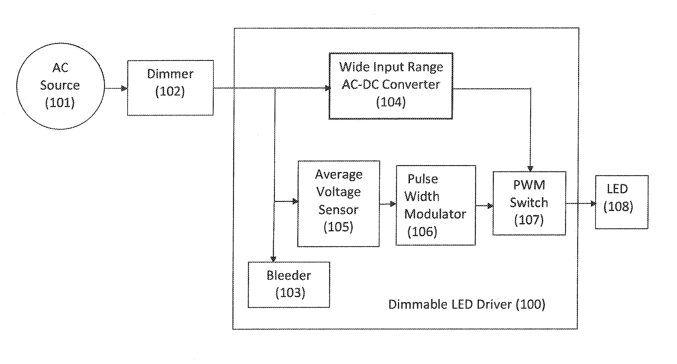
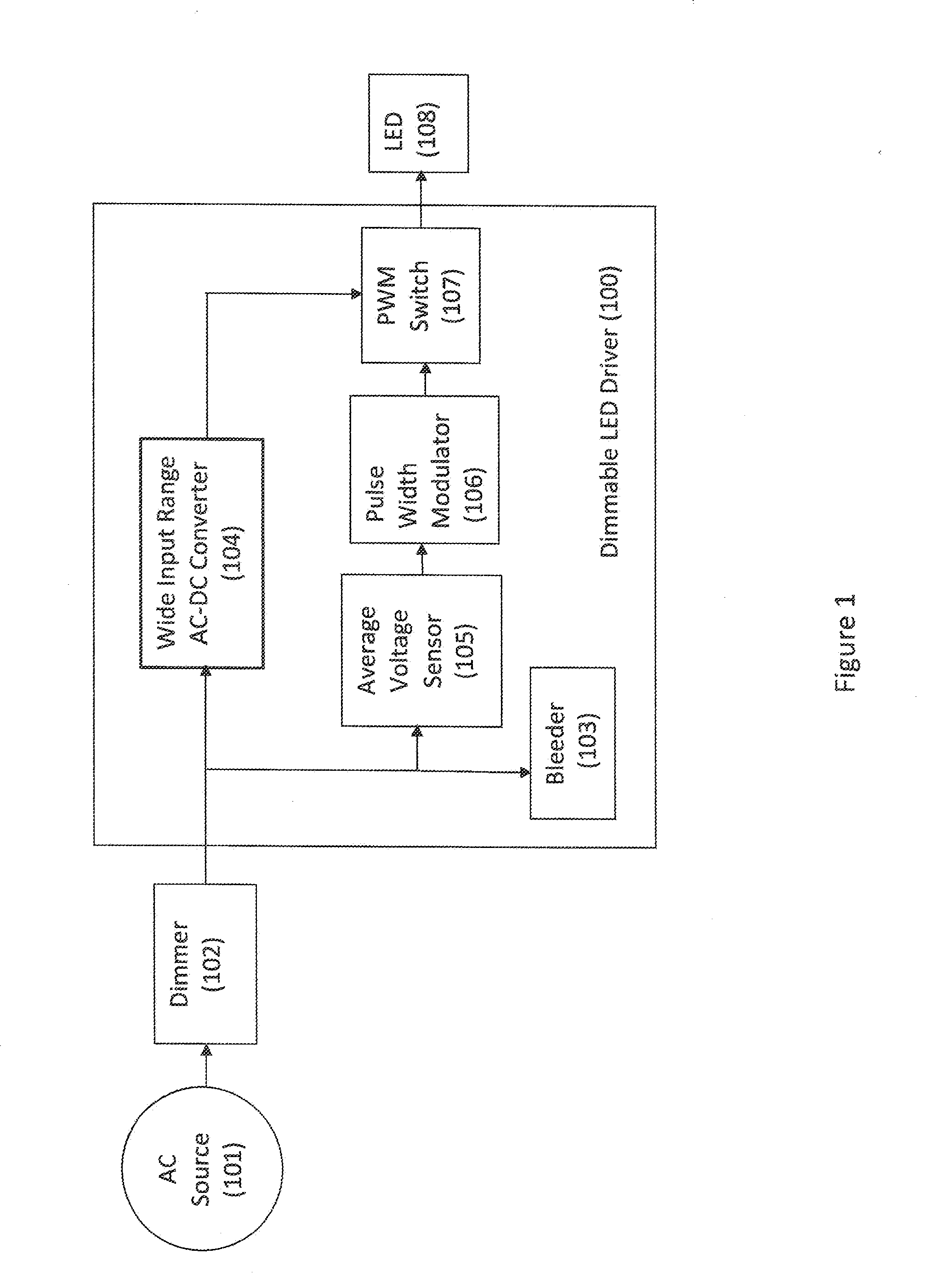
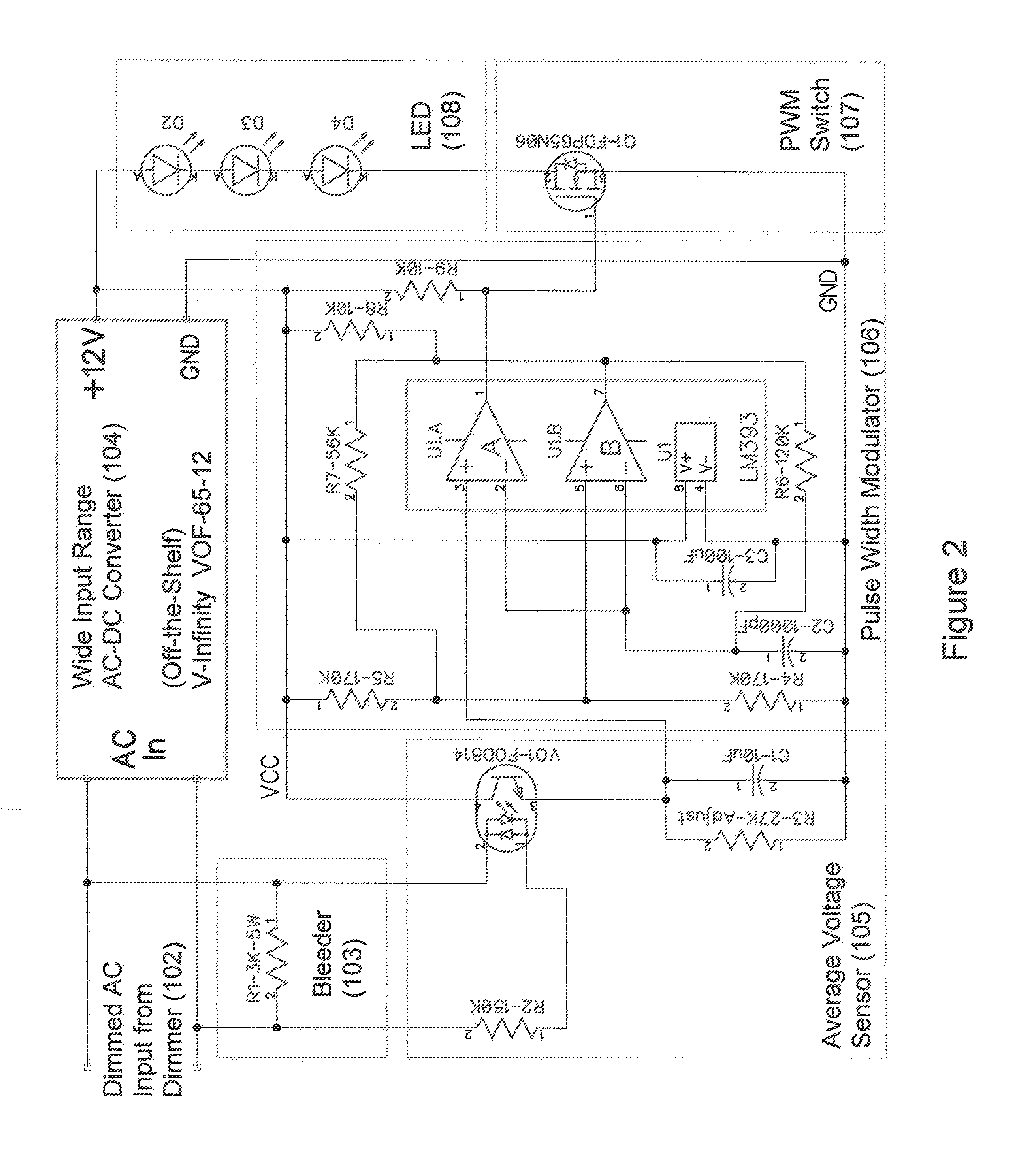
[0025]FIG. 1 shows how a dimmable LED driver can be made from a conventional AC-DC converter module by adding a few components. As shown in FIG. 1, the power from the AC power source (101) passes through Dimmer (102) and is fed into the input of the dimmable LED driver (100) made according to the current invention. The output of the dimmable LED driver (100) is connected to LED (108). Dimmer (102) can be any type of dimmer that can be used for dimming an incandescent lamp, including leading edge phase dimmers, trailing edge phase dimmers, or VARICs (variable output voltage transformers), as long as the average voltage fed into the dimmable LED drive (100) can be gradually reduced under user control. LED (108) can be one LED or any type of arrangement of LED arrays, including flexible LED strips or other type of LED lighting fixture that can be driven by a specific DC voltage (for example, 12V).

[0026]The dimmable LED driver (100) can be made from an AC-DC converter module (104) by ad...


PUM


Abstract

A constant voltage dimmable LED (Light Emitting Diode) driver is disclosed that is compatible with all types of dimmers, including conventional phase cut (TRIAC) dimmers, and behaves like a conventional constant voltage driver which can be connected to any size of LED load that has a matching voltage rating. The driver produces a continuous train of pulses for driving the LED load and obtains an averaged measure of the voltage at the AC input for controlling the duty cycle of the continuous train of pulses. Therefore, when the averaged measure of the voltage at the AC input is reduced by a dimmer, the duty cycle reduces, resulting in a dimmed LED. The driver can be created by adding a few components to a conventional wide input range AC-DC converter without or with very little modifications.

Description

CROSS-REFERENCE TO RELATED APPLICATION[0001]This application is a continuation application of and claims the benefit of priority to U.S. patent application Ser. No. 13 / 066,388, filed on Apr. 13, 2011, entitled “Constant Voltage Dimmable LED Driver”, which is incorporated by reference herein in its entirety.FIELD OF THE INVENTION[0002]The embodiments discussed herein relate to a power supply for driving light emitting diodes (LEDs).BACKGROUND OF THE INVENTION[0003]The use of LEDs in lighting applications is rapidly expanding, as they are much more efficient and have much longer life time than incandescent lamps. Compared with fluorescent lighting systems, LEDs also have an advantage that they do not contain harmful substances such as mercury.[0004]LEDs are primarily DC devices and usually require a much lower voltage than the mains AC power provided by utility companies. For this reason, a power supply or “driver” is needed for converting the mains AC power to a DC voltage or current...

Claims


Application Information

Patent Timeline
Patent Type & Authority Applications(United States)
IPC IPC(8): H05B33/08H05B44/00
CPCH05B33/0815H05B45/46H05B45/37Y02B20/30H05B41/2985H05B41/2855
Inventor LIU, GANG GARY
Owner LIU GANG GARY
Learn More