
Coordinate indicating apparatus and coordinate measurement apparatus for measuring input position of coordinate indicating apparatus

a technology of coordinate indicating apparatus and coordinate measurement apparatus, which is applied in the direction of instruments, computing, electric digital data processing, etc., can solve the problems of unintended operation error, screen glare, and problem of r-type touch screen

Active Publication Date: 2013-11-14
SAMSUNG ELECTRONICS CO LTD
View PDF12 Cites 36 Cited by
  • Summary
  • Abstract
  • Description
  • Claims
  • Application Information

AI Technical Summary

Benefits of technology

The present invention provides a coordinate indicating apparatus and a coordinate measurement apparatus that can determine the input positions of a stylus pen and a conductive object (such as a finger) using a single touch screen. Additionally, the apparatus can distinguish between different types of contact objects. This solves the problems of the prior art and provides more efficient and precise input for users.

Problems solved by technology

Among touch screens, the R type touch screen capable of recognizing a user's finger and a stylus pen has been widely used, but the R type touch screen is problematic in that there is screen glare due to an air space between Indium Tin Oxide (ITO) layers.
However, the C type touch screen has difficulty in physically distinguishing between a hand and a pen, resulting in an unintended operation error by a contact of the hand which may occur when the pen is used.
However, software does not completely resolve the unintended operation error generated due to the contact of the hand, and implementing the method including the separate measurement apparatus increases size, weight, and cost of the device, by requiring additional components.

Method used


Image

  • Coordinate indicating apparatus and coordinate measurement apparatus for measuring input position of coordinate indicating apparatus
  • Coordinate indicating apparatus and coordinate measurement apparatus for measuring input position of coordinate indicating apparatus
  • Coordinate indicating apparatus and coordinate measurement apparatus for measuring input position of coordinate indicating apparatus

Examples


Embodiment Construction

[0031]Hereinafter, various embodiments of the present invention will be described in detail with reference to the accompanying drawings. In the following description, the same or like elements are designated by the same or like reference numerals throughout the drawings. Further, detailed description of known functions and configurations is omitted to avoid obscuring the subject matter of the present invention.

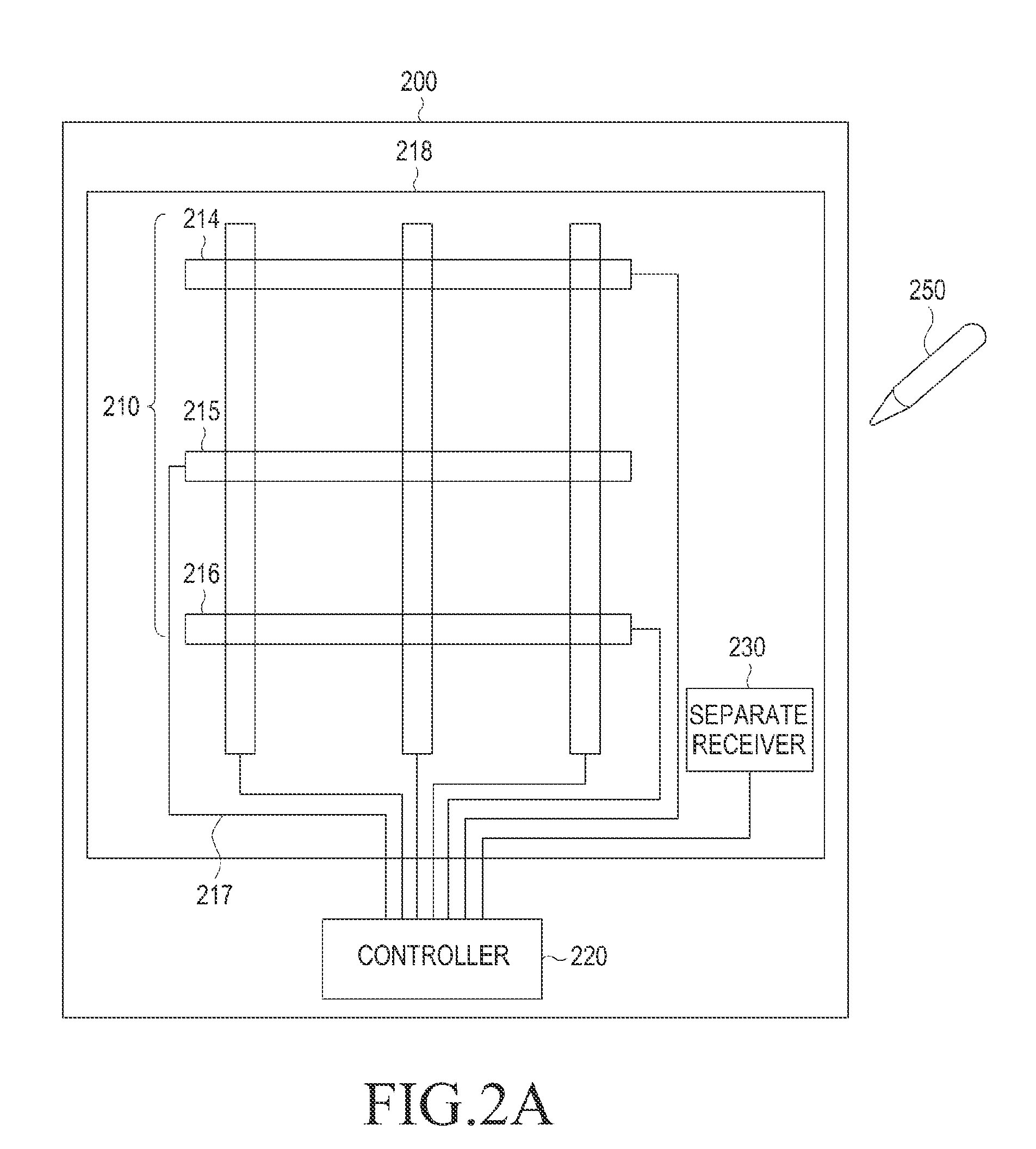
[0032]According to aspects of the present invention, a coordinate indicating apparatus and a coordinate measurement apparatus which determines input positions of a stylus pen and a conductive object while including only a single touch screen is provided. Further, a coordinate indicating apparatus and a coordinate measurement apparatus which distinguishes whether a type of contact object is a stylus pen or a finger is provided.

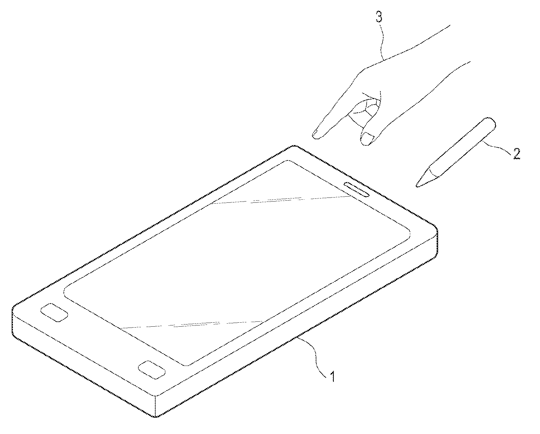
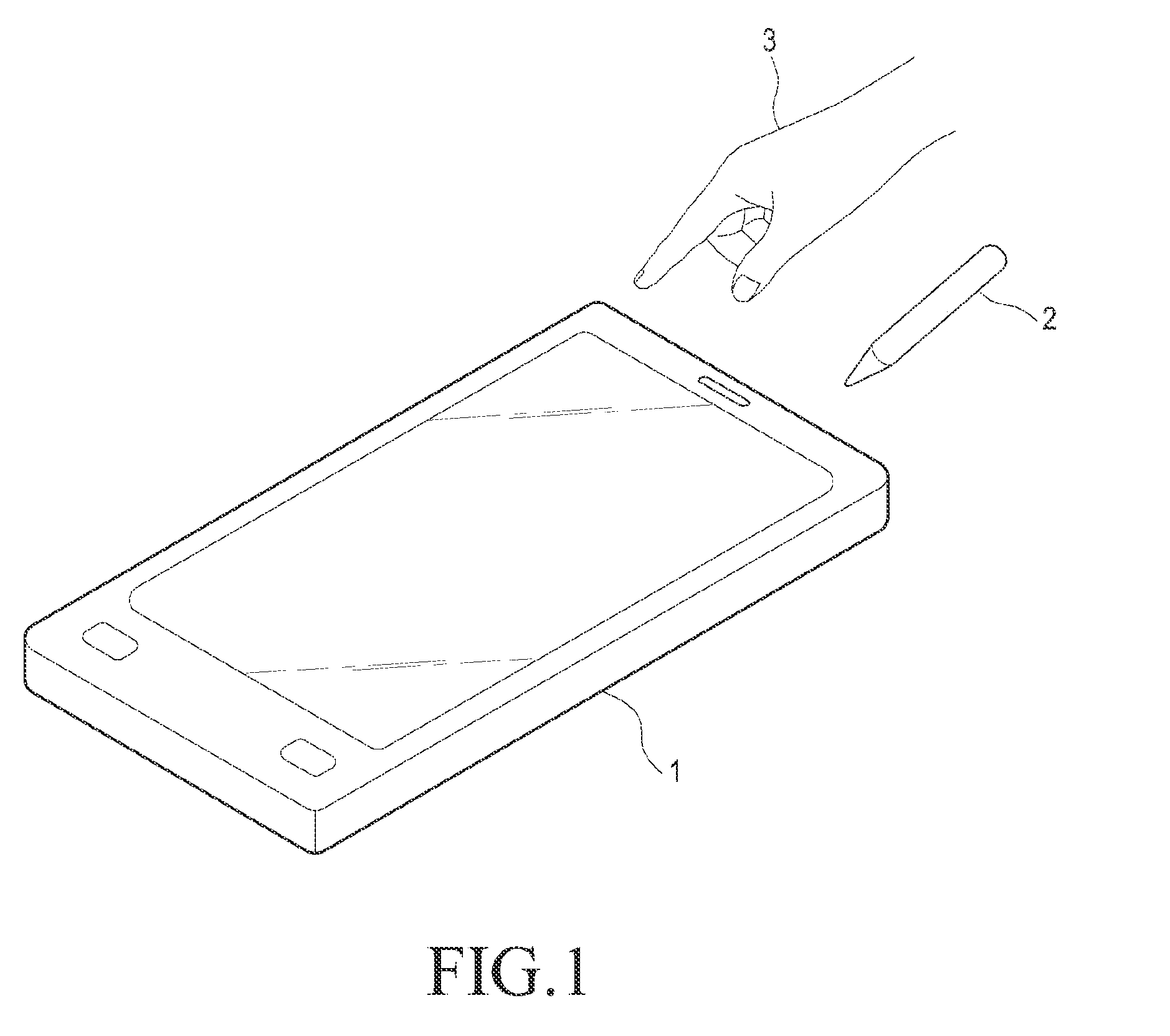
[0033]FIG. 1 is a diagram illustrating a coordinate indicating system according to an embodiment of the present invention. As illustrated in FIG. 1, a co...


PUM


Abstract

A coordinate measurement system including a coordinate indicating apparatus and a coordinate measurement apparatus for determining a position of a contact object including the coordinate indicating apparatus. The coordinate measurement apparatus includes a channel electrode unit including one or more electrodes, wherein capacitance of each of the one or more electrodes or capacitance between the one or more electrodes is changed based on a change in the position of the contact object, and a controller for applying an electrical signal to the channel electrode unit or measuring a reception signal input to the channel electrode unit. The coordinate indicating apparatus includes a conductive tip for forming capacitance with the one or more electrodes of the channel electrode unit, and a resonant circuit unit for generating identification information of the coordinate indicating apparatus, wherein the resonant circuit unit is connected to the conductive tip.

Description

PRIORITY[0001]This application claims priority under 35 U.S.C. §119(a) to Korean Application filed in the Korean Intellectual Property Office on May 11, 2012 and assigned Serial No. 10-2012-0050371, the entire disclosure of which is incorporated herein by reference.BACKGROUND OF THE INVENTION[0002]1. Field of the Invention[0003]The present invention relates generally to a coordinate indicating apparatus and a coordinate measurement apparatus for measuring an input position of the coordinate indicating apparatus, and more particularly, to a coordinate indicating apparatus such as a finger or a stylus pen and a coordinate measurement apparatus for measuring an input position of the coordinate indicating apparatus.[0004]2. Description of the Related Art[0005]Currently, devices such as a smart phone and tablet PC are actively under development with capability for a contact position measurement apparatus embedded therein. Specifically, the smart phone or the tablet PC generally includes ...

Claims


Application Information

Patent Timeline
Patent Type & Authority Applications(United States)
IPC IPC(8): G06F3/044
CPCG06F3/044G06F2203/04104G06F2203/04106G06F3/03545G06F2203/04105G06F3/0441G06F3/04166G06F3/04164G06F3/0442G06F3/0446G06F3/0447G06F3/038
Inventor KIM, GWAN-HYUNG
Owner SAMSUNG ELECTRONICS CO LTD
Learn More