Drive unit for switching element and method thereof

Active Publication Date: 2013-11-14
DENSO CORP
View PDF4 Cites 9 Cited by
  • Summary
  • Abstract
  • Description
  • Claims
  • Application Information

AI Technical Summary

Benefits of technology

[0010]The inventors of the present invention have conducted keen investigation, experimentation, and the like regarding the factors involved in the actual output current of the sense terminal becoming lower than an initially assumed value based on the current flowing between the input terminal and the output terminal of the terminal, in a situation in which excess current is flowing to the switching element. The inventors have found the factor to be the difference of electric potential between the input te

Problems solved by technology

When the excess current cannot be promptly detected,

Method used


Image

  • Drive unit for switching element and method thereof
  • Drive unit for switching element and method thereof
  • Drive unit for switching element and method thereof

Examples


first embodiment

[0022]A drive unit for a switching element according to a first embodiment of the present invention will be described with reference to the drawings. According to the first embodiment, the drive unit for a switching element is applied to a hybrid car providing both a motor as a main driving engine and an internal combustion engine (i.e. gasoline engine) as a supplemental driving engine.

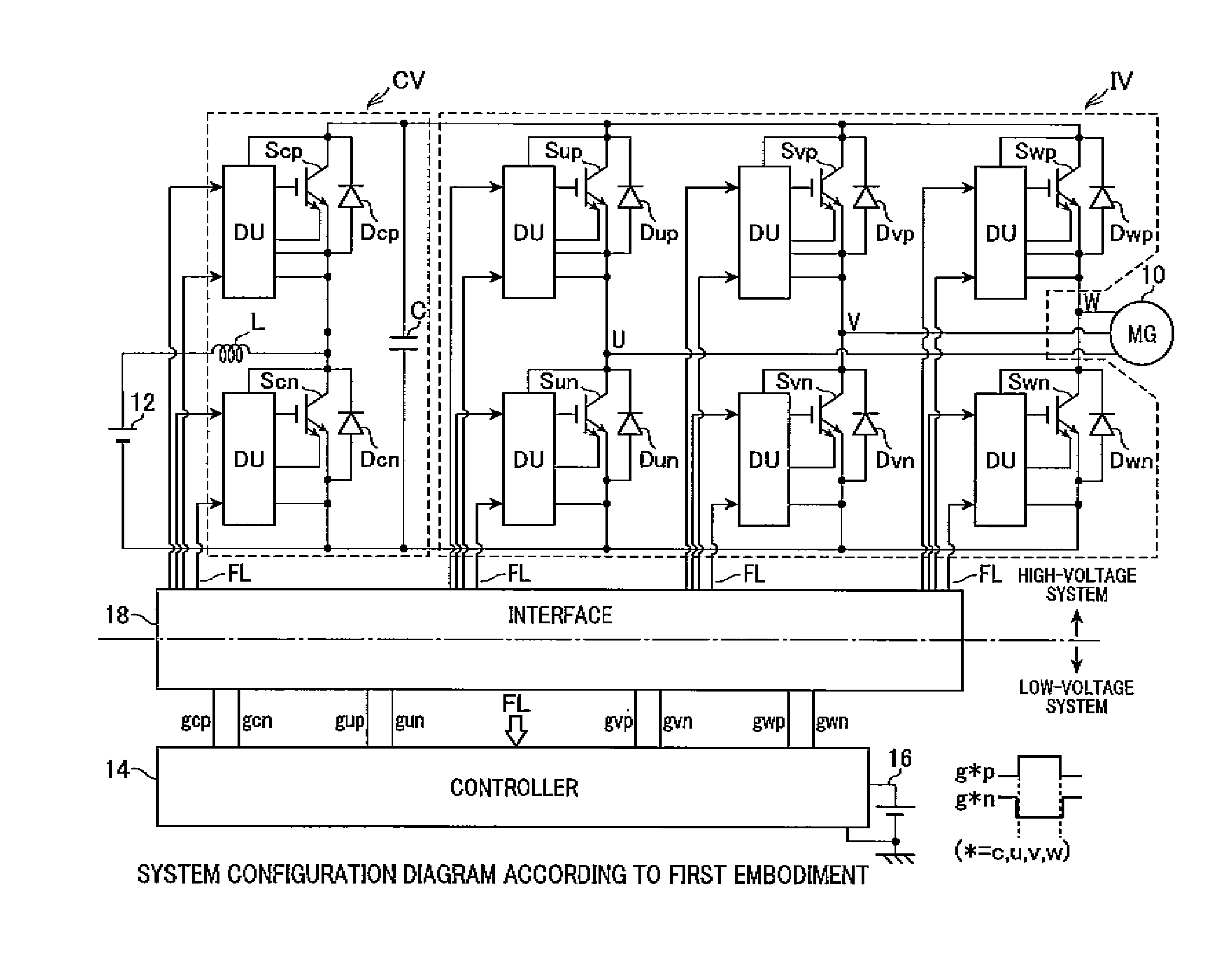
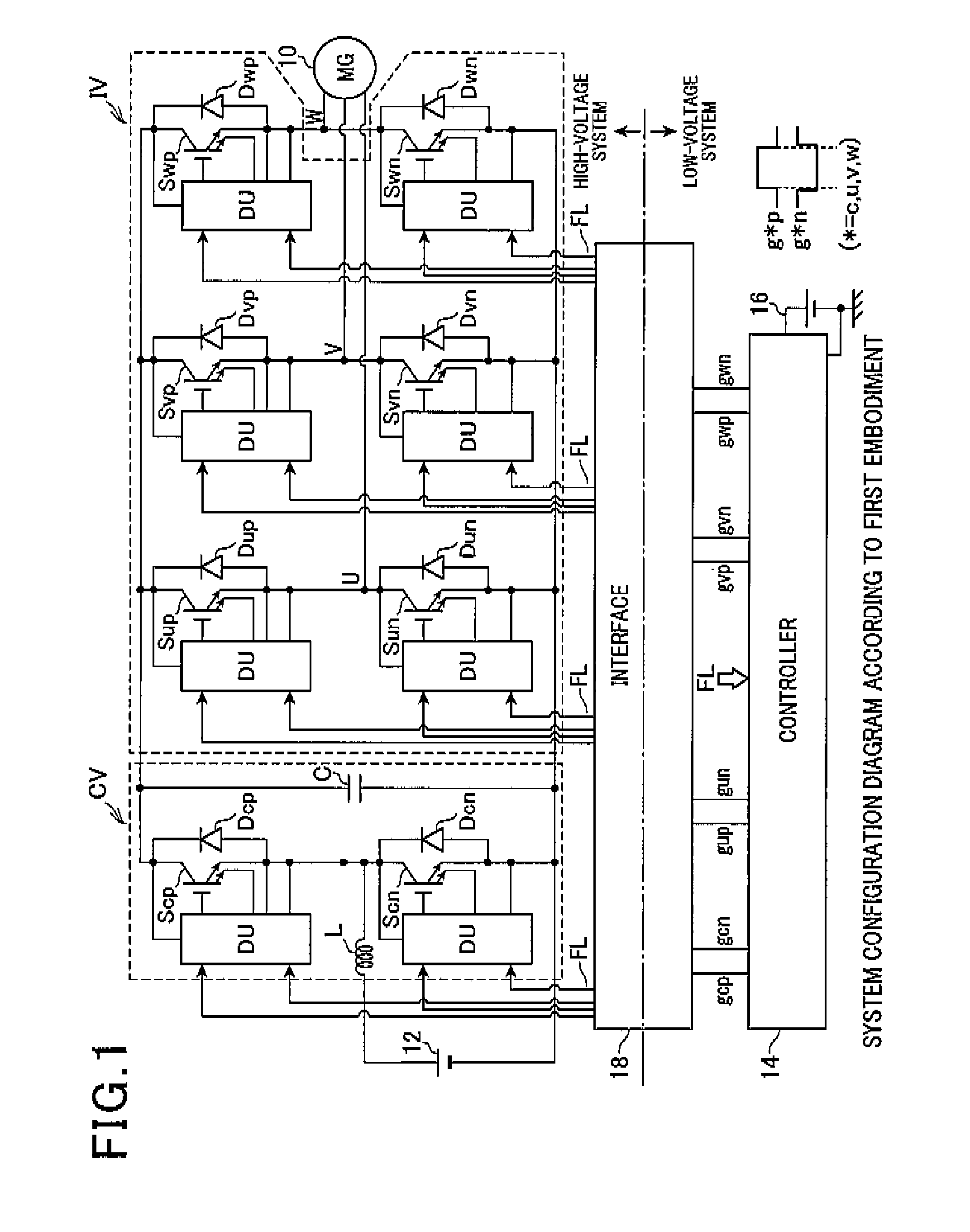
[0023]FIG. 1 shows an overall configuration of a system according to the first embodiment.

[0024]A motor generator (MG) 10 is configured to be capable of being set to two operating states: “power running mode” providing a function as a motor that is a cruising drive source and “electric power regenerating mode” providing a function as a power generator. The motor generator 10 receives electric power from a battery and is used as an electric motor, or is used as a power generator for charging the battery. These modes depend on the operating state required. According to the first embodiment, the motor ge...

second embodiment

[0063]A second embodiment will hereinafter be described with reference to the drawings, focusing on the differences with the above-described first embodiment.

[0064]According to the second embodiment, as the threshold voltage changing process, a process is performed in which the threshold voltage Vth is changed based on the collector-emitter voltage Vs when the switching element S*# is set to the ON state. The process is performed in light of the judgment regarding whether or not there is risk of delay in the detection of excess current being possible based on the collector-emitter voltage Vs when the switching element S*# is set to the ON state, as well.

[0065]Here, the reason that the judgment regarding whether or not there is risk of delay in the detection of excess current is possible will be described. The sense voltage Vse does not reach a voltage equal to or higher than the collector-emitter voltage Vce of when the switching element S*# is in the ON state. This is because a vol...

third embodiment

[0080]A third embodiment will hereinafter be described with reference to the drawings, focusing on the differences with the above-described second embodiment.

[0081]According to the third embodiment, the collector-emitter voltage Vs used in the threshold voltage changing process is corrected based on the element temperature TD calculated from the output voltage of the temperature-sensitive diode SD*#. This process is performed based on the tendency for the collector-emitter voltage Vce when the switching element S*# is in the ON state to ordinarily become lower, the higher the element temperature TD is, in relation to the same collector current Ice, as shown in FIG. 9.

[0082]FIG. 10 shows the procedures in the correction process performed by the drive control section 54. The drive control section 54 is hardware. Therefore, the process shown in FIG. 10 is in actuality performed by a logic circuit.

[0083]In the series of processing operations, first, at Step S26, the drive control sectio...


PUM


Abstract

The present application provides a drive unit for a switching element, the driving unit having a function that is capable of promptly detecting the flow of excess current. The unit is usable for an electrical rotating machine. A drive unit for a switching element, comprising: a sense terminal output current detecting means for detecting an output current of a sense terminal that outputs a minute current having correlation with a current flowing between an input terminal and an output terminal of a switching element; a switching element drive control means for restricting the driving of the switching element when the output current detected by the sense terminal output current detecting means exceeds a predetermined threshold value; and a threshold changing means for changing the threshold value on the basis of a difference of electric potential between the input terminal and the output terminal of the switching element.

Description

CROSS-REFERENCE TO RELATED APPLICATION[0001]This application is based on and claims the benefit of priority from earlier Japanese Patent Application No. 2012-108126 filed May 10, 2012, the description of which is incorporated herein by reference.BACKGROUND OF THE INVENTION[0002]1. Field of the Invention[0003]The present invention relates to a drive unit for a switching element having an excess current protection function that is capable of being applied to, for example, a rotating electrical machine.[0004]2. Description of the Related Art[0005]As shown, for example, in JP-B-3474775, as this type of device, a device is known that includes an excess current protection circuit that protects a switching element (such as an insulated-gate bipolar transistor [IGBT]) from excess current. Specifically, the device includes a resistor and a comparator. The resistor is connected between a sense terminal and an output terminal of the switching element. The comparator compares a sense voltage an...

Claims


Application Information

Patent Timeline
IPC IPC(8): H02H9/02
CPCH02H9/02H03K17/0828H03K2017/0806H03K2217/0027
Inventor ASAKO, YOUSUKEMAEBARA, TSUNEO
Owner DENSO CORP
Why Eureka
Try Eureka