Compact high-power diode/thyristor rectifier architecture

a high-power diode and rectifier technology, applied in the direction of power conversion systems, electrical equipment, conversion construction details, etc., can solve the problems of limiting the benefit of the rectifier arm, difficult to obtain fuses, and current electronic component technology not making it possible to produce high-current diodes or thyristors, etc., to improve the imbalance of components and improve the compactness of the converter-rectifier

Active Publication Date: 2013-11-14
ALSTOM TECH LTD
View PDF17 Cites 8 Cited by
  • Summary
  • Abstract
  • Description
  • Claims
  • Application Information

AI Technical Summary

Benefits of technology

[0049]Here the invention relates mainly to the architecture of the rectifier and aims to make it possible to connect a large number of components in parallel without exceeding the maximum imbalance value imposed by users. The invention typically aims to connect in parallel 20, 24 or more components with a maximum imbalance between 20% and 30%.

Problems solved by technology

This would limit the benefit of the rectifier arm.
However, current electronic component technology does not make it possible to produce high-current diodes or thyristors 5.
Moreover, it is very difficult to obtain fuses 7 with a very high current rating if the rectified voltage is increased.
Such parallel connection of the components gives rise to problems of balancing the current between the unidirectional components 5 of the same rectifier arm. FIG. 3 gives an example of the current distribution for a typical rectifier arm including n diodes.
This increases the imbalance.
Finally, beyond a certain current value, existing rectifier structures have a number n of unidirectional components 5 to be connected in parallel that leads to a prohibitive imbalance.
The above prior art structures are unsatisfactory because it is hardly possible to go beyond 16 or 18 components in parallel without the imbalance becoming prohibitive.

Method used


Image

  • Compact high-power diode/thyristor rectifier architecture
  • Compact high-power diode/thyristor rectifier architecture
  • Compact high-power diode/thyristor rectifier architecture

Examples


Embodiment Construction

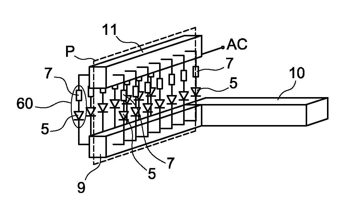
[0090]The invention relates firstly to a three-phase Graëz-bridge rectifier arm designed to be included in a converter-rectifier. The rectifier arm is described below as such or as if included in the converter-rectifier. Generally speaking, FIGS. 7 to 12, illustrating the invention, are diagrams of a single rectifier arm of the invention and not of the converter-rectifier as a whole.

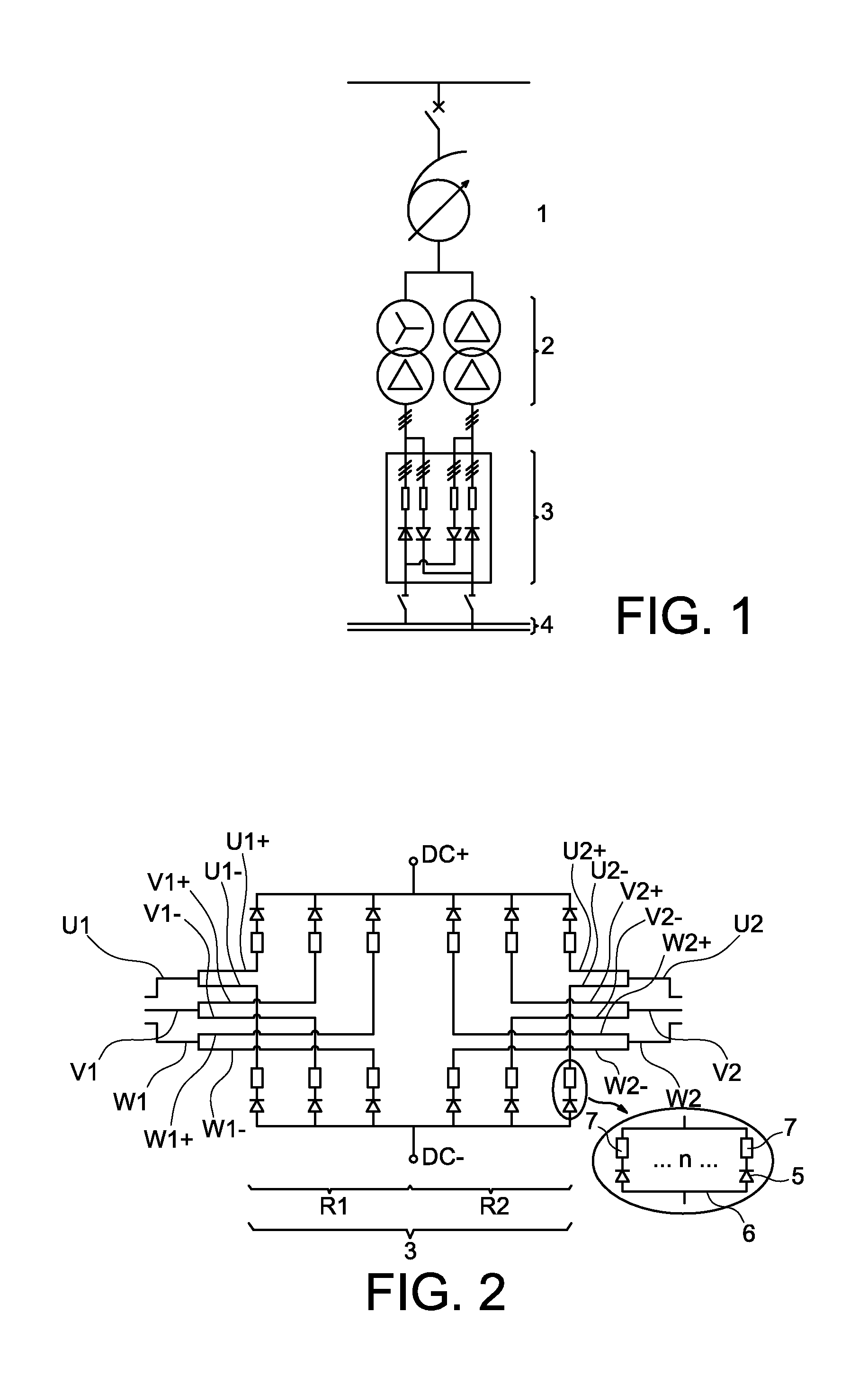
[0091]As shown in FIG. 2, a three-phase Graëz-bridge rectifier R1, R2 is formed of six rectifier arms connecting each of two AC terminals of each of the three phases U1, V1, W1 or U2, V2, W2 fed with alternating current to two DC terminals of an electrical circuit to be fed with direct current. The three-phase Graëz bridge therefore has a positive DC terminal DC+, seen with a positive polarity by the electrical circuit, and a negative DC terminal DC−, seen with a negative polarity by the electrical circuit. Each phase U1, V1, W1, U2, V2, W2 includes two rectifier arms U1+, U1−, V1+, V1−, W1+, W1−, U2+, U...


PUM


Abstract

A Graëtz-bridge converter-rectifier in which at least one rectifier arm situated between a single AC terminal and a single DC terminal includes multiple unidirectional electronic components connected in parallel and connected on one side to the DC terminal by means of a conductive component set and on the other side to the AC terminal. The invention is characterized in that the component set for at least one rectifier arm includes a plurality of separate component busbars each having at least one end connected to the DC terminal, the unidirectional components being divided between the component busbars into as many component sets connected in parallel as there are component busbars.

Description

TECHNICAL FIELD[0001]The present invention relates to the field of high-current and / or high- or medium-voltage power rectifiers.[0002]This field covers rectifiers able to deliver direct currents up to 110 kiloamps (kA) and direct current (DC) voltages that may exceed 2200 volts (V).[0003]The invention relates to the architecture of high-power (100 megavoltamp (MVA)) rectifiers used for feeding direct current to electro-intensive processes requiring high-power DC power supplies. Thus the invention may be used to supply power to aluminum or non-ferrous metal (copper, zinc, chlorine) electrolysis plants. The invention may also be used to supply power to other electro-intensive processes requiring high-power DC power supplies such as direct current arc furnaces.[0004]In the description below the use of such rectifiers for supplying power to an electrolysis plant is used as one particular example.DESCRIPTION OF THE PRIOR ART[0005]An electrical power supply for an electrolysis plant consi...

Claims


Application Information

Patent Timeline
Patent Type & Authority Applications(United States)
IPC IPC(8): H02M7/08
CPCH02M7/08H02M7/003
Inventor MARIADASSOU, PRITHUDEVAUTOUR, JOEL
Owner ALSTOM TECH LTD
Why Eureka
Try Eureka