Suction and irrigation device

a technology of which is applied in the field of hand-held suction and irrigation device, can solve the problems of increasing surgical risk, disturbing or interrupting treatment, and shivering of the hand, so as to improve the durability of the device, facilitate the operation, and facilitate the effect of operation

Inactive Publication Date: 2013-11-14
UNIV BERN VERWDIREKTION
View PDF4 Cites 59 Cited by
  • Summary
  • Abstract
  • Description
  • Claims
  • Application Information

AI Technical Summary

Benefits of technology

[0013]The suction and irrigation device according to the invention can be operated easily from a first position to a second position and back with one hand without the need of changing finger positions on the device or even to find a grip for holding the device. Thus the suction device can be kept still during surgery and other applications. Advantageously, the valve body is simple to be connected to the suction and irrigation pipes of the device.
[0036]Preferably, upon acting a mechanical force upon the push element the movable magnetic element is moved in a direction parallel to a wall including the irrigation passage until it covers the suction passage. For that purpose, the angle between the axes of the passages is preferably in the range of 80-100°, most preferably 90°. This allows for a simple construction and ensures reliable interaction between the magnetic element and the mouths of the passages being contacted by the movable element.

Problems solved by technology

In same cases a lot of force is needed to actuate the switch or valve which may lead to shivering of the hand and therefore of the suction and irrigation device.
This can disturb or interrupt the treatment and even increase surgical risk, if the instrument is used together with a surgical microscope and therefore small movements of the instrument may lead to unwanted excursions in microscopical view.

Method used


Image

  • Suction and irrigation device
  • Suction and irrigation device
  • Suction and irrigation device

Examples


first embodiment

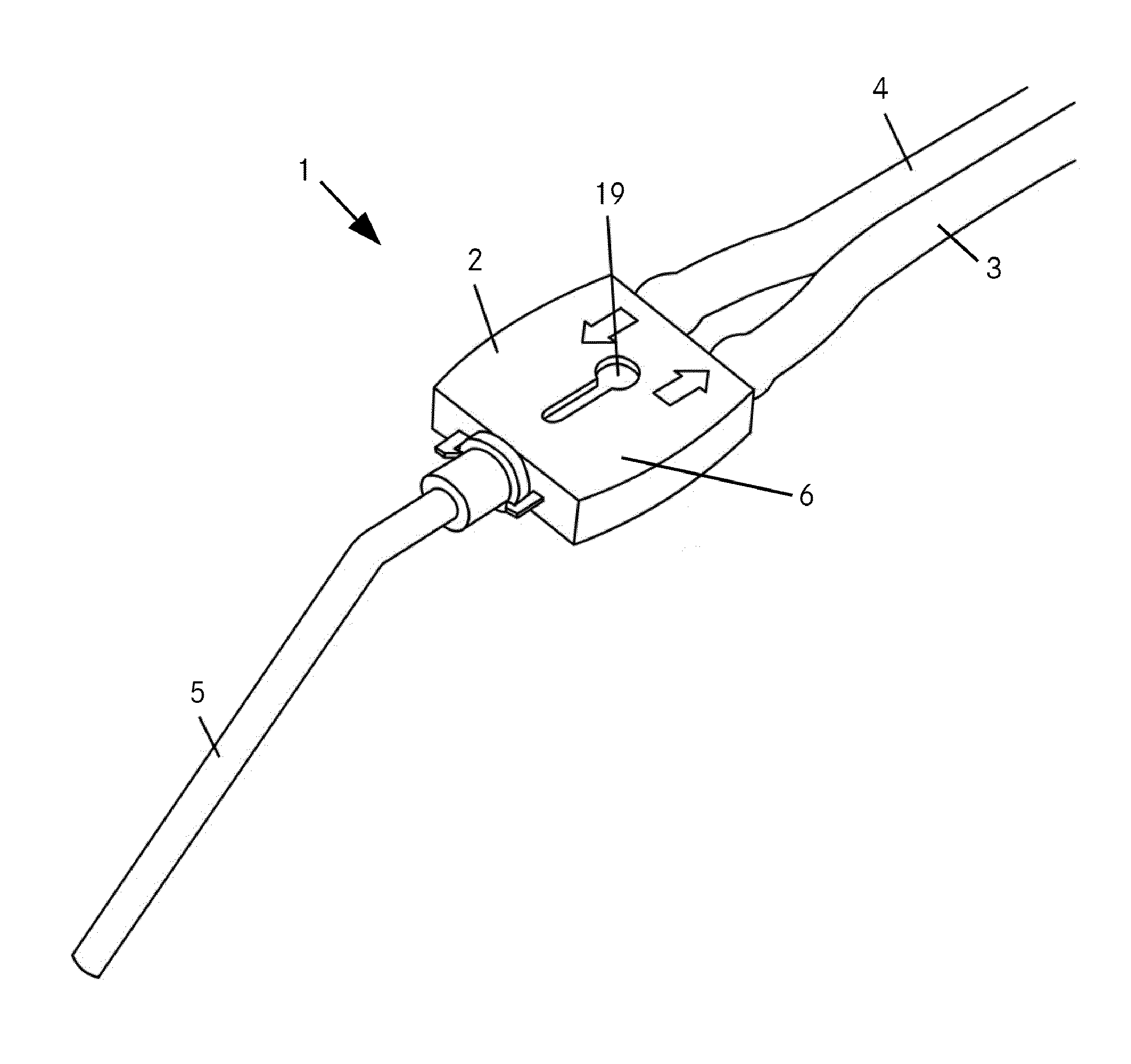
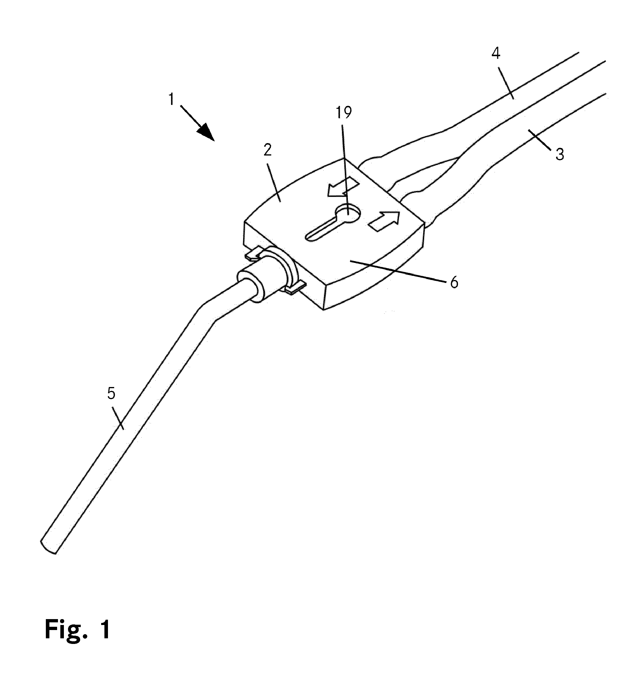
[0053]In FIG. 1, a suction and irrigation device 1 is shown comprising a valve body 2 with a connected proximal irrigation pipe 3, a connected proximal suction pipe 4 and a distally connected suction / irrigation tube 5. The irrigation pipe 3, the suction pipe 4 and the suction / irrigation tube 5 are attached to the valve body 2 by connectors, for example a Luer lock or similar port. The valve body 2 is designed as a rectangular body comprising a large area at the top and the bottom and four lateral surfaces connecting top and bottom. The large top area is designed as an elastically deformable push surface 6 according to the invention. The distal lateral surface comprises the distally connected suction / irrigation tube 5 and the proximal lateral surface comprises the proximally connected irrigation and suction pipes 3 and 4. The size of the large area and the push surface 6 respectively is about 2×2 cm and the height of the lateral surfaces is about 0.5 cm. The valve body is made of sil...

second embodiment

[0064]The FIGS. 6A-6C are schematical illustrations of a valve body of a suction and irrigation device according to the invention. The FIG. 6A shows a cross-sectional view in a plane at about half the height of the valve body and extending parallel to the top surface as well as two views onto the front and back surfaces of the valve body. The FIG. 6B shows a cross-section along the plane A-A perpendicular to the top surface. The FIG. 6C shows a cross-section along the plane B-B perpendicular to the top surface as well as to the cross-section of FIG. 6B. The FIG. 6D shows a cover for the valve body.

[0065]The valve body 102 is made from PVC. Its footprint is oblong with straight lateral edges and rounded front (distal) and back (proximal) edges. The base surface 121 of the valve body 102 is continuous over the entire footprint. The top surface 122 features a number of blind hole like openings, namely a valve compartment 123 having a rectangular footprint, arranged close to the front e...

third embodiment

[0076]The FIG. 8A-8D are schematical illustrations of a valve body of a suction and irrigation device according to the invention. The FIG. 8A shows a top view as well as two views onto the front and back surfaces of the valve body. The FIG. 8B shows a cross-section in a plane perpendicular to the top surface of the valve body, extending along A-A, the FIG. 8C shows a cross-section in a plane parallel thereto, along B-B. The FIG. 8D shows a cross-section in a plane parallel to the top surface along C-C. The FIG. 8E shows a cover for the valve body.

[0077]The valve body 202 is made from PVC. Its footprint is oblong with straight lateral edges and rounded front (distal) and back (proximal) edges. The base surface 221 of the valve body features a blind hole like opening, namely a suction compartment 225, having a substantially rectangular footprint. The top surface 222 features two blind hole like openings, namely a valve compartment 223 having a circular footprint, arranged close to the...


PUM


Abstract

A suction and irrigation device for medical use comprises a valve body with an irrigation passage and a suction passage. At least one irrigation pipe and at least one suction pipe are connectable to the irrigation passage and the suction passage by connections at a proximal side of the valve body. A suction / irrigation tube is connectable to the irrigation passage and the suction passage at a distal side of the valve body by at least one further connection. A valve assembly is provided within the valve body, which in a first position opens the suction passage and closes the irrigation passage and in a second position closes the suction passage and opens the irrigation passage. The device comprises at least one push element which interacts with at least one movable element of the valve assembly, whereas the movable element is movable by mechanical force acted upon the push element such, that the push element activates the valve assembly from one position to the other position.

Description

CROSS-REFERENCE TO RELATED APPLICATIONS[0001]This application claims priority to European Application No. 10192824.0 filed Nov. 26, 2010 and to PCT Application No. PCT / EP2011 / 070952 filed Nov. 24, 2011, all of which are incorporated herein by reference and made a part hereof.BACKGROUND OF THE INVENTION[0002]1. Field of the Invention[0003]The invention relates to a suction and irrigation device for medical use, in particular to a handheld suction and irrigation device operated by a medically trained person.[0004]2. Description of the Related Art[0005]Suction and irrigation devices are regularly used in several medical fields, for example in surgery, dentistry or general medical care. Such devices comprise a suction line and an irrigation line connected to a proximal side of a handhold, while a tip-hole is provided on a distal side, which is directed to the treatment area. The suction line is connected to a vacuum device to suck fluids through the tip-hole and the irrigation line is c...

Claims


Application Information

Patent Timeline
Patent Type & Authority Applications(United States)
IPC IPC(8): A61M3/02
CPCA61M3/0283A61M1/7415A61M1/7411A61M1/774A61M1/772
Inventor STIEGLITZ, LENNART HENNINGSPIEGELBERG, ANDREAS
Owner UNIV BERN VERWDIREKTION
Why Eureka
Try Eureka