Method for Operating a Compressed Air Brake System

a brake system and compressed air technology, applied in the direction of automatic control systems, process and machine control, instruments, etc., can solve the problems of more computational power and consequently more expensive ecu for the compressor controller

Inactive Publication Date: 2013-11-14
WABCO GMBH
View PDF11 Cites 11 Cited by
  • Summary
  • Abstract
  • Description
  • Claims
  • Application Information

AI Technical Summary

Benefits of technology

[0042]The present invention accordingly comprises the various steps and the relation of one or more of such steps with respect to each of the others, and embodies features of construction, combination

Problems solved by technology

This requires more computational power and a consequ

Method used


Image

  • Method for Operating a Compressed Air Brake System
  • Method for Operating a Compressed Air Brake System
  • Method for Operating a Compressed Air Brake System

Examples


Embodiment Construction

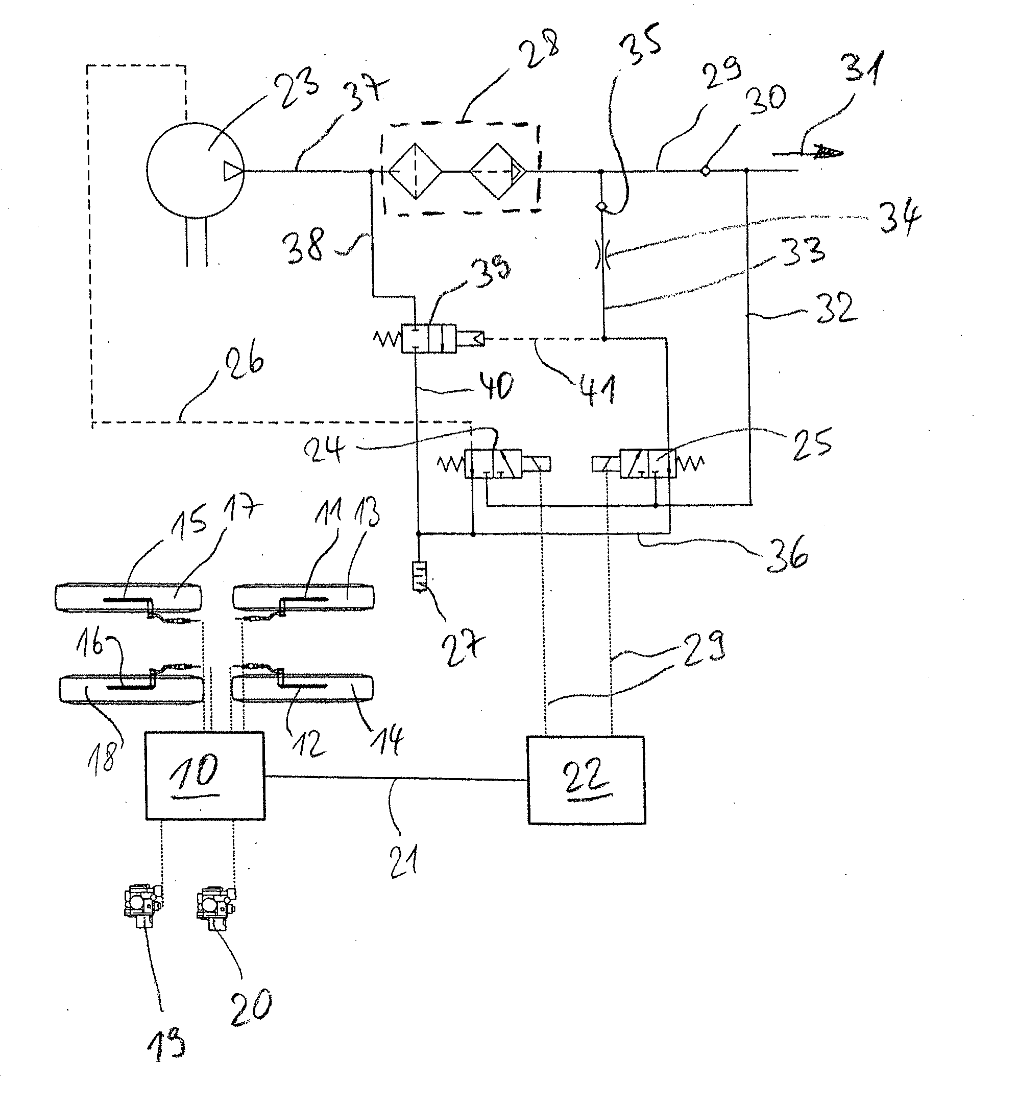
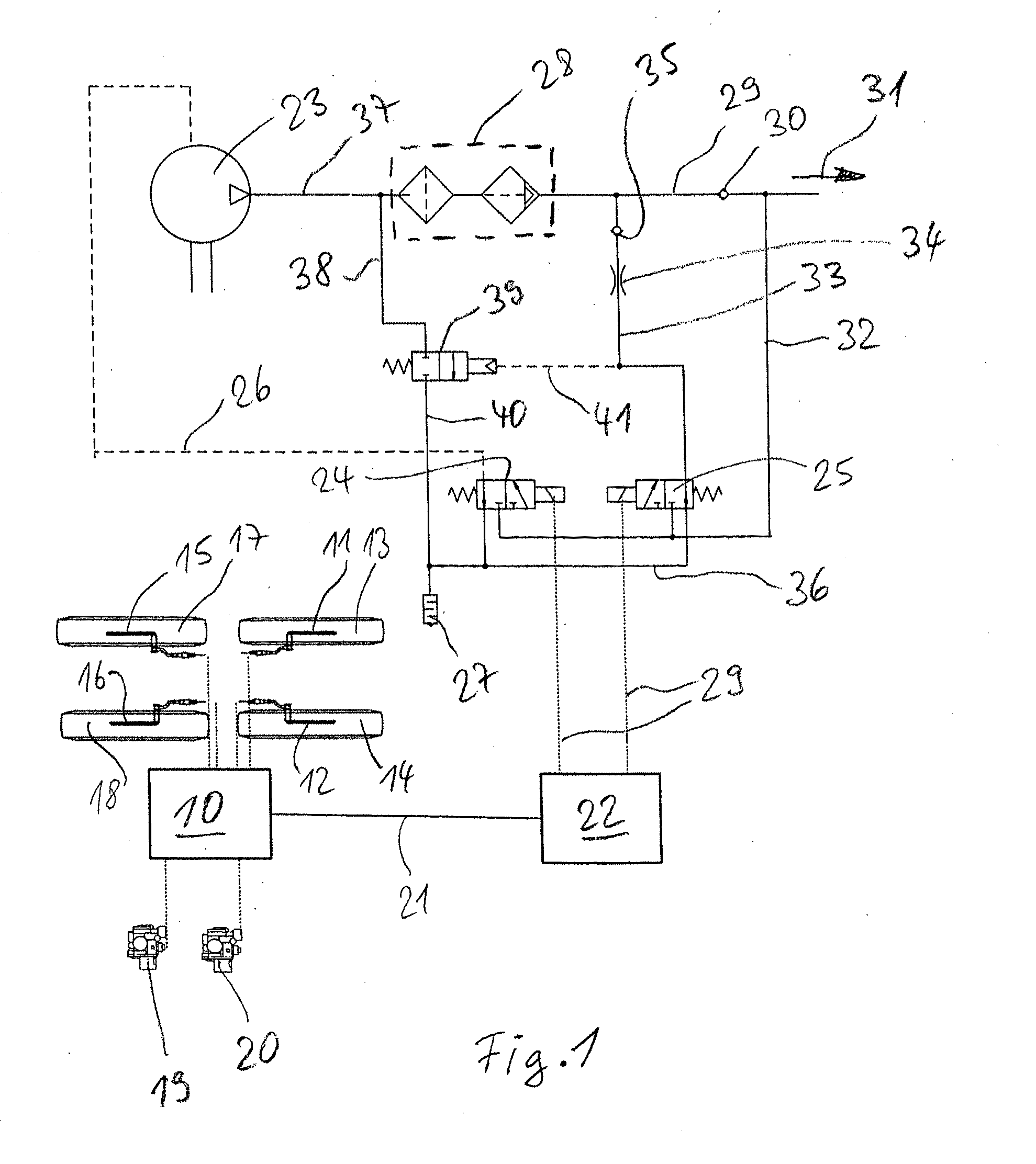
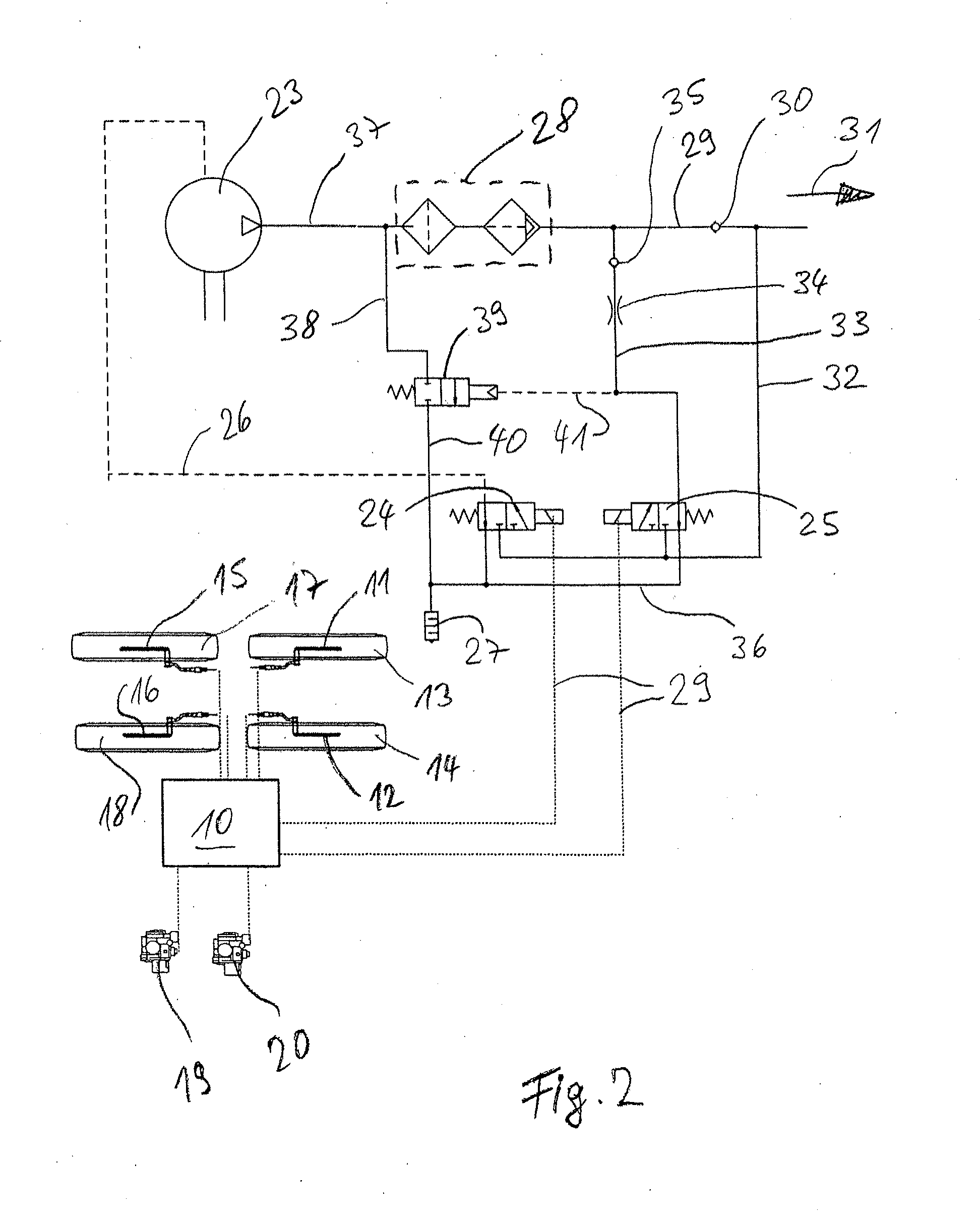
[0077]Referring now to the drawing figures, FIGS. 1 and 2 show exemplary embodiments of compressed air brake systems for a service brake in a motor vehicle. A brake control device 10 with closed-loop braking intervention control system, analogous to an ABS or EBS, directly reads out data from wheel speed sensors 11, 12 at driven wheels 13, 14 and from wheel speed sensors 15, 16 at following wheels 17, 18. The brake control device actuates in a known fashion pneumatic valves for regulating the function of compressed air brakes (not shown). These pneumatic valves are referred to here as modulators 19, 20.

[0078]In the embodiment depicted in FIG. 1, the brake control device 10 is connected via a CAN bus 21 to a control device 22 for an air conditioning system. Alternatively or additionally, the control device 22 can be provided for a compressor controller.

[0079]The switching over of a compressor 23 between feeding mode and idling mode is controlled by a solenoid valve 24, which, for rea...


PUM


Abstract

A method for operating a compressed air brake system in a motor vehicle equipped with a brake control device includes regulating the generation of compressed air and/or the supply of compressed air into a storage container and, in particular, the regeneration of an air conditioning system, using a compressor controller, and carrying out calculations for the compressor control in the brake control device.

Description

CROSS-REFERENCE TO RELATED APPLICATION[0001]This application claims the benefit of DE 10 2012 009 186.9 filed on May 10, 2012, the disclosure of which is hereby incorporated herein by reference in its entirety.FIELD OF THE INVENTION[0002]The present invention generally relates to methods for operating a compressed air brake system in a motor vehicle.BACKGROUND OF THE INVENTION[0003]Components of a motor vehicle compressed air brake system include, inter alia, a compressed air storage container, a compressor and a compressor controller. In addition, an air conditioning system may be present, in particular with an air dryer. The compressor controller is typically integrated into an electronic control unit (ECU), which is provided for it. In addition to the ECU for the compressor controller, further ECUs for other functions are present in the vehicle, in particular a brake control device, preferably with a closed-loop braking intervention controller and an engine control device. The va...

Claims


Application Information

Patent Timeline
IPC IPC(8): B60T13/26B60W10/30B60W30/18B60W10/184
CPCB60T13/268B60W10/184B60W10/30B60W30/18172B60W2600/00B60T17/004B60T17/02B60W2556/00
Inventor FEYERABEND, KONRADSTRUWE, OTMAR
Owner WABCO GMBH
Why Eureka
Try Eureka